info@biomedres.us
+1 (502) 904-2126
One Westbrook Corporate Center, Suite 300, Westchester, IL 60154, USA
Site Map
 ISSN: 2574 -1241
ISSN: 2574 -1241
ISSN: 2574 -1241
Received: July 13, 2026; Published: July 24, 2026
*Corresponding author: Qiang Yan, Talos Industry Corporation is a global technology company focused on the research, development, and commercialization of advanced wind turbine and energy storage systems, USA
DOI: 10.26717/BJSTR.2026.66.010322
This paper proposes a jet-driven rolling-wheel concept as a potential alternative to conventional impellers in steam turbines. In the proposed design, steam enters multiple inlet passages distributed over the conical surface of a rolling wheel and exits through corresponding outlet passages located near the circumferential side, thereby generating torque through jet reaction and fluid-solid interaction. The rotating wheel then drives an electrical generator through a shaft-based transmission arrangement. Compared with conventional multi-stage coaxial impeller systems, the proposed concept is intended to simplify rotor geometry, reduce manufacturing complexity, and enable modular deployment. The same design principle may also be extendable to gas-driven rotary systems beyond steam turbines. A preliminary analytical model is presented to estimate the relationships among steam density, flow area, outlet velocity, thrust, torque, and rotational speed. Under the simplifying assumptions adopted in this study, the calculated results suggest that the concept may have potential for compact and distributed power-generation applications. However, the present work is conceptual and exploratory. Further validation through thermodynamic analysis, compressible-flow modeling, computational fluid dynamics, and experimental testing is required before engineering feasibility can be established.
Keywords: Steam Turbine; Jet-Driven Wheel; Rolling Wheel; Impeller Alternative; Torque Generation; Modular Power Generation
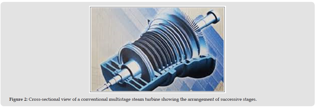
The continuing growth in electricity demand, particularly in data- intensive and distributed applications, has increased interest in power-generation systems that are efficient, economically competitive, and deployable within shorter time frames. Conventional steam turbines remain one of the dominant technologies for large-scale power generation, but they are often associated with complex rotor structures, demanding manufacturing requirements, and limited flexibility in compact or modular implementations. In conventional steam-turbine design, high-pressure steam expands through multiple stages and transfers energy to a sequence of impellers mounted on a common shaft. As steam pressure and density decrease during expansion, the specific volume increases. Accordingly, downstream stages are typically designed with progressively larger flow areas and impeller diameters in order to accommodate the changing steam volume while maintaining acceptable flow conditions. This approach is well established, but it also reflects the geometric and aerodynamic constraints of blade-based energy-conversion systems. Another limitation of conventional multi-stage coaxial rotors is that blade-tip speed differs substantially between stages. As a consequence, the ratio between blade-tip speed and local steam velocity may vary across the machine, which can influence aerodynamic performance. Additional losses may arise from tip leakage, secondary flow structures, viscous dissipation, and the redirection of steam by stationary blade rows.
Furthermore, the manufacture of high-temperature bladed rotors can be technically challenging and costly, particularly when compactness or rapid deployment is required. To explore a different approach to gas-to-torque conversion, this paper proposes a jet-driven rolling wheel as a possible substitute for conventional impellers. Instead of relying on blade surfaces to extract work from the steam, the proposed concept uses multiple internal inlet-outlet passages distributed around a rolling wheel. Steam enters the wheel, flows through inclined passages, and exits near the outer circumference with a strong tangential component, thereby generating rotational torque through jet reaction. The concept is intended to simplify the rotating structure and provide a basis for modular energy-conversion units. The purpose of this paper is to present the structural concept, describe its operating principle, and provide preliminary analytical examples. The present analysis is intended as a first-order conceptual study rather than a complete engineering validation (Figures 1 & 2).
Figure 1
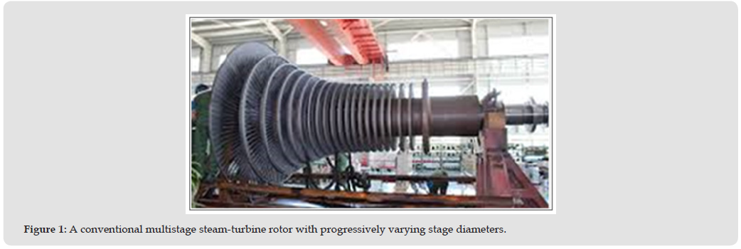
Figure 2
Conventional steam and gas turbines rely on well-established turbomachinery principles in which pressure energy and kinetic energy are converted into shaft work through staged blade rows. Their performance is governed by thermodynamic efficiency, stage loading, blade geometry, rotor-stator interaction, and flow matching across multiple stages. In addition to conventional bladed turbines, alternative rotary energy-conversion concepts have also been proposed. Among them, bladeless or boundary-layer-driven devices, such as Tesla-type turbines, are often cited as examples of simplified rotor geometry. However, such concepts operate primarily through viscous drag along rotating surfaces, which differs fundamentally from the present rolling-wheel concept. The design proposed in this paper relies on distributed internal passages and directed outlet jets to generate circumferential reaction torque. Other reaction-driven rotary devices also demonstrate that fluid jets can produce torque when the discharge direction is appropriately arranged. Nevertheless, the use of a conical rolling wheel with multiple inlet-outlet passage pairs for modular steam-based power generation appears to be relatively unexplored. The present work therefore focuses on defining this concept and presenting a preliminary analytical discussion of its potential operating behavior. At this stage, the proposed concept should be understood as an exploratory addition to the broader family of unconventional rotary energy-conversion devices rather than as a validated competitor to established turbine architectures.
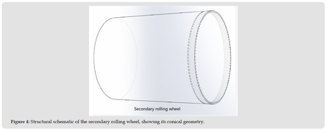
The proposed system consists of rolling-wheel stages that may be arranged singly or in sequence. In the configuration discussed in this paper, two types of rolling wheel are considered: a primary rolling wheel and a secondary rolling wheel. The primary wheel includes a cylindrical front section together with a conical rear section, whereas the secondary wheel is conical in shape. The cylindrical front section of the primary wheel is intended to receive steam from a flattened inlet nozzle. Multiple inlet passages are distributed around the conical surface of the rolling wheel (Figures 3 & 4). Each inlet is connected to a corresponding outlet through an internal inclined passage. The outlets are positioned near the circumferential side of the wheel, close to the maximum radius, in order to maximize the torque arm. The internal passages are oriented as nearly parallel as possible to the local circumferential tangent so that the discharged steam retains a substantial tangential velocity component. This inlet-outlet arrangement is central to the proposed concept. Rather than transferring momentum to external blades, the steam is guided through the rotating body itself and discharged in a direction intended to generate torque directly. The number, size, and angular orientation of the passages may be selected according to the required mass flow rate, target speed range, and manufacturing constraints.
Figure 3
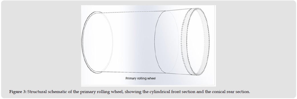
Figure 4
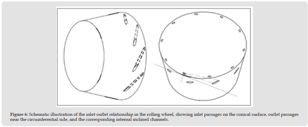
A key design feature is the one-to-one correspondence between inlet passages and outlet passages. Steam enters through inlets located on the conical surface and exits through outlets positioned near the circumferential side of the wheel. Each inlet-outlet pair is connected by an internal passage with an inclined orientation. The outlet location is chosen to be as close as practicable to the outer circumference so that the effective moment arm is maximized. The passage orientation is intended to increase the tangential component of the exiting jet and thereby enhance the reaction torque. Depending on design objectives, the inlet area may be larger than the outlet area so that the flow is accelerated as it approaches the discharge side. From an engineering perspective, the proposed passage geometry would need to be optimized with respect to flow losses, manufacturability, structural integrity, and rotational balance. In the present paper, however, the geometry is discussed qualitatively and used primarily as the basis for a simplified analytical model (Figures 5 & 6).
Figure 5
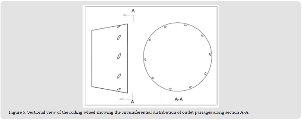
Figure 6
The rolling-wheel concept may have potential applications in several categories of gas-driven rotary machinery.
• It may be explored as an alternative to conventional impeller stages in steam turbines, particularly in systems where compactness, modularity, or manufacturing simplicity is of interest.
• The concept may be relevant to gas-turbine-type systems, especially in cases where the thermal and mechanical limitations of conventional high-temperature bladed rotors present design challenges. • The same operating principle may be extendable to other gas-driven torque-generating devices in which directed flow can be used to produce rotational motion.
At the current stage, these applications should be regarded as hypothetical and exploratory. Their practical feasibility would depend on detailed thermodynamic performance, high-speed mechanical behavior, material limits, manufacturing methods, and system-integration considerations.
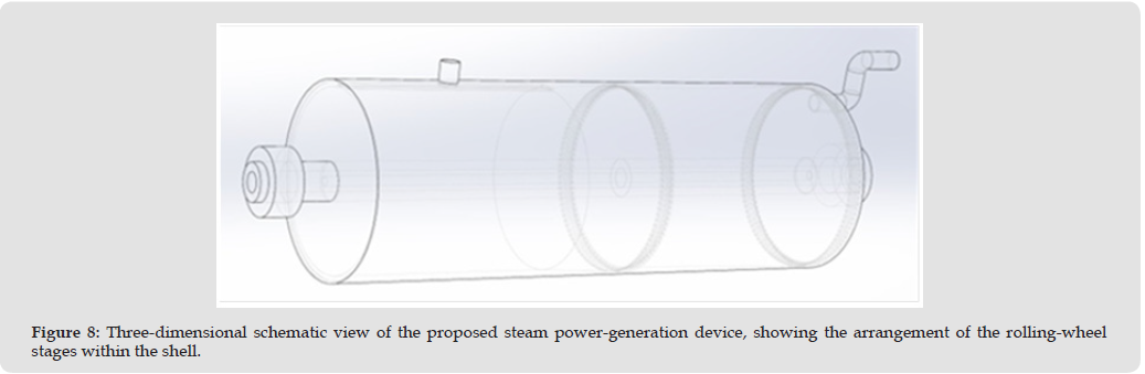
The proposed power-generation device consists of a shell, a main shaft with bushings, one or more rolling wheels, and one or more generators. In the primary stage, high-pressure steam enters a groove at the front of the rolling wheel through a flattened duckbill nozzle. The steam is then distributed into multiple inlet passages on the conical surface of the wheel. As the steam travels through the internal passages, it is guided toward outlets located near the circumferential side. Because the outlet passages are inclined relative to the local tangent, the discharged steam produces a jet-reaction force with a tangential component, causing the wheel to rotate. The rolling wheel then transmits torque to an electrical generator. Steam discharged from the primary wheel may be routed into a secondary wheel or into another downstream module. In this way, the system may be configured either as a standalone power-generation unit or as a sequence of modular stages. The concept therefore combines internal flow guidance, reaction torque generation, and distributed electrical conversion. In simplified form, the proposed operating mechanism depends on three effects: • Jet-reaction torque generated by high-velocity discharge from the outlet passages. • Fluid-solid interaction, including viscous effects between the steam and the rolling-wheel surfaces. • Stage-wise or modular power extraction through independent or semi-independent generator coupling. The present paper does not claim that this mechanism is necessarily more efficient than conventional turbines under practical operating conditions. Rather, it proposes the concept as an alternative configuration that merits further investigation (Figures 7 & 8).
Figure 7
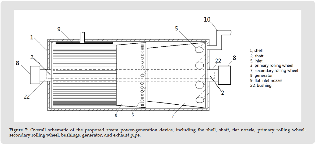
Figure 8
To provide a first-order estimate of performance, a simplified analytical model is introduced. The model is intended only for conceptual evaluation and does not constitute a complete thermodynamic or aerodynamic treatment.
Mass-Flow Relation
The mass flow rate is expressed as m-dot = rho A v, where m-dot is the mass flow rate, rho is the steam density, A is the total flow area, and v is the outlet velocity. Thus, A = m-dot / (rho v).
Jet Thrust
Under a simplified momentum approximation, the jet thrust is estimated as F = m-dot v. This expression neglects inlet tangential momentum, pressure-thrust terms, and nonuniform flow effects.
Torque
The torque at radius r is approximated by T = Fr.
Angular velocity and rotational speed
Assuming that the circumferential speed is comparable to the outlet steam velocity, the angular velocity is estimated as omega = v / r, and the rotational speed is n = omega x 60 / (2pi).
Power
The shaft power is estimated by P = omega T. If an overall correction factor eta is introduced to account in an approximate way for transmission and electrical-conversion effects, the electrical power may be estimated as Pe = eta omega T.
These relations are used here only to illustrate the scaling behavior of the concept. A rigorous model would also require steam-property relations, enthalpy-drop analysis, compressible-flow treatment, nozzle and passage losses, rotordynamic analysis, and generator- matching considerations.
Assume that the internal pipe cavity has a cross-sectional area of 0.5 m2 and a diameter of 0.8 m. The inlet steam temperature is 200°C, the inlet pressure is 1 MPa, the mass flow rate is 10 kg/s, and the steam density is taken as 7.8 kg/m3. For the present estimate, the steam density near the outlet is assumed to be approximately 7 kg/ m3, and the desired outlet velocity is 300 m/s. Using A = m-dot / (rho v), the required nozzle outlet area is A = 10 / (7 x 300) = 0.004762 m2, which is equivalent to 4762 mm2. If the total outlet area is divided among 100 channels, then the outlet area per channel is A1 = 4762 / 100 = 47.62 mm2. For a circular outlet, the equivalent diameter is approximately 7.8 mm. If the steam density decreases further to 6 kg/ m3 while the total outlet area remains unchanged, the outlet velocity becomes approximately 350 m/s. Assuming a maximum wheel radius of 0.4 m, the angular velocity is 875 rad/s, corresponding to a rotational speed of approximately 8350 rpm. The total thrust is estimated as 3500 N, and the torque is 1400 N·m. If the effective torque is approximated as 1500 N·m, including an assumed contribution from fluid-solid interaction, and if an overall correction factor of 0.75 is adopted, then the electrical power output of the primary rolling wheel is estimated as approximately 1 MW. If the steam then enters a secondary rolling wheel and the density is assumed to decrease from 6 kg/m3 to 5 kg/m3 while the outlet area remains unchanged, the outlet velocity becomes 420 m/s. The corresponding thrust is 4200 N, the torque is 1680 N·m, and the angular velocity is 1050 rad/s. This corresponds to a rotational speed of approximately 10,000 rpm. The electrical power is then estimated as about 1.3 MW. If a third rolling- wheel stage is added and the steam density is assumed to decrease further to 3 kg/m3, the outlet velocity becomes 700 m/s. The thrust is 7000 N, the torque is 2800 N·m, and the angular velocity is 1750 rad/s, corresponding to approximately 16,700 rpm. The corresponding electrical power is estimated as about 3.6 MW. Accordingly, the total estimated electrical output of the three-stage rolling-wheel configuration is approximately 5.9 MW.
Consider the same unit structure, nozzle geometry, and inlet conditions as in Example 1, with a duckbill-nozzle outlet velocity of 300 m/s. Assume that the density of the steam leaving the primary rolling wheel decreases to 4 kg/m3. Under the same constant-area assumption, the outlet velocity of the primary rolling wheel becomes 525 m/s. The corresponding angular velocity is 1312.5 rad/s, which corresponds to a rotational speed of approximately 12,500 rpm. The thrust is estimated as 5250 N, and the torque is 2100 N·m. Using the same overall correction factor of 0.75, the corresponding electrical power is estimated as approximately 2 MW. Next, assume that steam with a density of 4 kg/m3 enters the secondary rolling wheel and that the density at the outlet decreases to 3 kg/m3. The outlet velocity then becomes 700 m/s. The angular velocity is 1750 rad/s, and the rotational speed is approximately 16,700 rpm. The total thrust is 7000 N, and the total torque is 2800 N·m. The corresponding electrical output is then estimated as about 3.6 MW. Therefore, the total estimated electrical power output of the two-stage rolling-wheel configuration in this example is approximately 5.6 MW.
Assume that the steam power generator contains only two rolling- wheel stages, and that the steam discharged from the secondary stage is routed through piping into a second steam power generator. In this arrangement, the outlet flow from the first generator becomes the input source for the second generator. From Example 1, the combined output of the first and second rolling-wheel stages in the first generator is approximately 2.3 MW. At the outlet of the second rolling wheel in the first generator, the steam density is assumed to decrease to 5 kg/m3. Instead of entering a third rolling-wheel stage, this steam is conveyed to a second steam power generator having the same duckbill-nozzle geometry as the first device. Steam with a density of 5 kg/m3 is then assumed to enter the primary rolling wheel of the second generator. If the density of the steam leaving the primary rolling wheel of the second generator decreases from 5 kg/m3 to 4 kg/ m3, the outlet velocity becomes 525 m/s. Using the same calculation approach as in the preceding examples, a steam outlet velocity of 525 m/s corresponds to an estimated electrical output of approximately 2 MW for the primary wheel of the second generator. If the density of the steam leaving the secondary rolling wheel of the second generator decreases from 4 kg/m3 to 3 kg/m3, the outlet velocity becomes 700 m/s. Under the same assumptions, this corresponds to an electrical output of approximately 3.6 MW for the secondary wheel. Accordingly, the total output of the second generator is estimated as 5.6 MW, and the combined output of the two generators connected in series is estimated as 7.9 MW. This example illustrates the modularity of the proposed concept. However, the practical feasibility of serial energy extraction in this manner would require verification through a full thermodynamic energy-balance analysis.
The performance estimates presented in the preceding examples are based on simplified momentum and kinematic relations. However, for a steam-driven power-conversion device, the predicted electrical output must remain consistent with the thermodynamic work available from the steam. For an inlet state of approximately 1 MPa and 200°C, the steam is in the superheated region. Standard superheated steam tables are therefore more appropriate than saturated tables for estimating the inlet enthalpy and entropy. A representative engineering estimate for this state is an inlet specific enthalpy of approximately 2818 kJ/kg and an inlet specific entropy of approximately 6.69 kJ/kg·K, consistent with widely used thermodynamic tables and engineering references.
The total power predicted in Example 1 is approximately 5.9 MW for a steam mass flow rate of 10 kg/s. This corresponds to a specific work output of about 590 kJ/kg. In order for this prediction to be thermodynamically feasible, the steam would need to experience an effective enthalpy drop at least of this magnitude after accounting for all nozzle, passage, mechanical, and electrical losses. Under an idealized upper-bound interpretation, the required enthalpy drop may be estimated from P divided by m-dot, yielding approximately 590 kJ/kg. If this value is subtracted from the inlet enthalpy, the outlet enthalpy corresponding to the predicted total output becomes approximately 2228 kJ/kg.
This is a useful consistency check, but it should not be interpreted as a demonstrated outlet state, because the actual outlet pressure, quality, entropy change, kinetic-energy carryover, and internal irreversibilities have not yet been established. A more rigorous evaluation would require the outlet pressure or pressure ratio for each stage, followed by an isentropic or polytropic expansion analysis using steam tables or an IAPWS-based property model. The resulting theoretical enthalpy drop would then need to be compared against the estimated electrical output after accounting for system efficiency. Without this step, the current calculations remain conceptual rather than predictive. Therefore, the power estimates reported in this study should be interpreted as preliminary conceptual estimates only. A rigorous feasibility assessment would require specification of inlet and outlet steam states, calculation of enthalpy change using steam tables or an equation of state, estimation of nozzle and passage losses, verification of compressible-flow constraints, and confirmation that the predicted electrical output does not exceed the available thermodynamic work.
The present work has several important limitations.
• The analysis is conceptual and does not yet include a full thermodynamic treatment of steam expansion.
• The internal flow within the inlet-outlet passages has not yet been analyzed using compressible-flow theory or computational fluid dynamics.
• The mechanical behavior of the rolling wheel at high rotational speed has not yet been evaluated.
• The current analysis does not yet consider manufacturing tolerances, passage-machining limitations, material selection, sealing, leakage, or long-term reliability under high-temperature steam conditions.
• The predicted electrical output has not yet been verified experimentally. Consequently, the present study should be regarded as an initial design hypothesis and analytical exploration rather than a validated engineering solution [1-10].
The rolling-wheel concept represents an alternative approach to steam-driven torque generation. Instead of relying on conventional blade rows, the proposed configuration uses distributed internal passages to convert steam flow into circumferential reaction torque. From a conceptual standpoint, this arrangement may offer advantages in structural simplicity and modularity. However, the simplified calculations presented here should not be interpreted as evidence of superior practical efficiency relative to existing turbine technology. Steam turbines have been optimized over many decades, and any alternative concept must be evaluated against stringent thermodynamic, aerodynamic, structural, and economic criteria. The main contribution of the present work is therefore not the demonstration of a validated performance breakthrough, but the introduction of a new geometric and functional concept for steam-energy conversion. Its practical value will depend on whether future analyses and experiments can confirm adequate efficiency, acceptable mechanical integrity, and competitive system-level cost. In this sense, the rolling-wheel concept should be regarded as a candidate architecture for further study rather than as an immediately deployable replacement for conventional turbine stages.
Table 1: CT Exam Protocol.
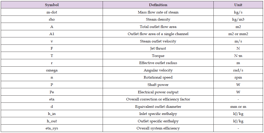
This paper has presented a jet-driven rolling-wheel concept as a possible alternative to conventional impellers in steam-turbine applications. The proposed design uses multiple inlet-outlet passage pairs distributed around a conical rolling wheel to generate rotational torque through jet reaction and fluid-solid interaction. A simplified analytical model was introduced to estimate the relationships among steam density, outlet area, discharge velocity, thrust, torque, rotational speed, and electrical output. Under the assumptions used in the present examples, the concept appears to merit further investigation as a modular and compact steam-energy-conversion approach. At the same time, the present study remains preliminary. The analysis does not yet include full thermodynamic consistency, compressible-flow modeling, structural verification, or experimental validation. Future work should therefore focus on detailed thermodynamic analysis, CFD simulation, high-speed mechanical assessment, and prototype testing in order to determine whether the concept can provide practical advantages over conventional turbine technology.

International Association of Landscape Archaeology, Czech Glass Society, Czech Republic

Department of Chemistry, Semenov Institute of Chemical Physics, USSR Academy of Sciences, Moscow, Russia

Department of Educational Sciences, Research Centre Qualities of Teachers, School of Education – HAN, Nijmegen, Netherlands

Associate Professor at Department of Breast and Thyorid Surgey, Chongqing General Hospital, China

Neurology, LA BioMed Research Institute, USA





 Abstract
 PDF
PDF