info@biomedres.us
+1 (502) 904-2126
One Westbrook Corporate Center, Suite 300, Westchester, IL 60154, USA
Site Map
Received: July 06, 2017; Published: July 10, 2017
Corresponding author: Ee Chon Teo, School of Mechanical & Aerospace Engineering, Nanyang Technological University, College of Engineering, 50 Nanyang Avenue, Singapore 639798
DOI: 10.26717/BJSTR.2017.01.000181
In human, the thoracolumbar junction (TLJ) is a transitional region where the normal kyphotic thoracic region shifts to the normal lordotic lumbar region; the coronally oriented facet joints of the thoracic region transform to the sagitally oriented facet joints of the lumbar; and the relatively immobile thoracic region changes to the relatively mobile lumbar region. The different anatomical characteristics at the functional spinal units (FSUs) of T11- T12 and T12-L1 provide an opportunity to study the associations between pathoanatomical changes in these two levels. Hence, it is of interest to investigate the biomechanical responses of the spinal motion segments T11-T12 and T12-L1, which possess the transitional vertebra T12, to determine whether the biomechanical kinematic properties reflect these anatomical changes between these FSUs. The movement of a FSU is dependent upon several parameters, namely its complex geometry, facet articulations and material characteristics of the ligament us tissues, intervertebral discs, and upon the applied load vectors.
Accordingly, this study aimed to use a validated FE models of thoracolumbar junctional T11- T12 and T12-L1 functional spinal units (FSUs) validated under physiological loading modes: flexion, extension, lateral bending and axial rotation, and to compare the kinematics in terms of the locations and loci of instantaneous axes of rotation (IARs).
Keywords: Thoracolumbar Junction; Finite Element; Axis of Rotation; Functional Spinal Unit
Abbreviations: TLJ: Thoraco Lumbar Junction; FSU: Functional Spinal Units; IAR: Instantaneous Axes of Rotation
The locations and loci of T12-L1 differ greatly from those of T11-T12. In sagittal plane, the locations and loci of the IARs were located below the intervertebral disc for T11-T12, situated in the intervertebral disc for T12-L1. In transverse plane, they fell in the medio-anterior region of the movable vertebra T11 for the T11-T12, and located near the cortical shell of the upper vertebra T12 for T12-L1 [1], (Figures 1 & 2).
It is known that the anatomic geometrical structure of a FSU defines it motion and related biomechanical responses. Hence, some differences in anatomical features of these two FSUs may account for the variation in loci [2]. At level T11-T12, the facet articulation is essentially oriented in the coronal plane; while in the T12-L1 segment, the facet joint surfaces are sagitally aligned. For the intervertebral disc, at T11-T12, the anterior height is slightly larger than the posterior height; whereas, at T12-L1, the anterior height is greater than the posterior height, which results a lordotic angle. These different orientations of the facets and the geometry of interveterbral discs demonstrate the difference in loci at the two levels, (Figures 3 & 4).
These findings offer an insight to better understanding the kinematics of the human thoracolumbar spine; provide clinically relevant information for the evaluation of spinal stability and implant devices functionality, and the biomechanical load effect on spinal deformity.
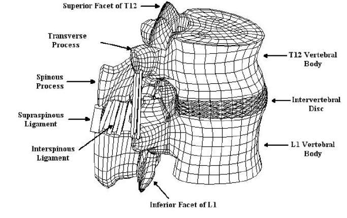
Figure 1: T12-L1 FE model.
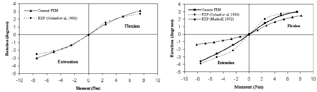
Figure 2: Angular motion of T11-T12 and T12-L1.
Figures 1 & 2: below show T12-L1 FE model and a validation study on the biomechanical responses of T11-T12 and T12-L1 under flexion/extensions, respectively.
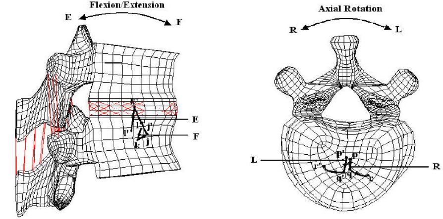
Figure 3: T11-T12 Locus of axis of rotation under F/E and A Rotation.
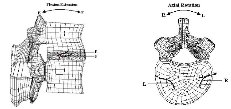
Figure 4: T12-L1 Locus of axis of rotation under F/E and A Rotation.
Figures 3 & 4: shows the locus of axis of rotation of T11-T12 and T12-L1 models under two loading configurations of flexion/ extension and axial rotation, respectively.


