info@biomedres.us
+1 (502) 904-2126
One Westbrook Corporate Center, Suite 300, Westchester, IL 60154, USA
Site Map
Received: January 17, 2025; Published: January 23, 2025
*Corresponding author: Martyushov SN, Moscow Aviation Institute, National Research University, Moscow, Russia
DOI: 10.26717/BJSTR.2025.60.009437
For many years idea of detonation engine was in center of attention of researchers. The detonation fuel cycle is more energetic preferable than the Briton cycle used in aviation and rocket engines. So, simplicity of construction and energetic effectiveness make the development of detonation engine constructions very perspective. Detonation initiation can be achieved by different ways, namely by focusing of pulse jet inside sphere-shape resonator (Fujiwara, et al. [1]) or spin detonation engine, in which detonation waves propagate inside axis -symmetrical region in radial direction (Zhdan, et al. [2]), by electric discharges or by specification of region inside engine: channels with obstacles, ring or U-tube form of channels (Frolov, et al. [3]). Progress in the construction of detonation engine partly consist of developing numerical algorithms of high order of accuracy which can produce precisely results of numerical simulation of gas flow inside the engine. This numerical algorithm demands also using of sophisticated mathematical models.
During numerical simulation of deflagration appearance, it is necessary to take into account influence of viscous turbulence effects, dissipation of energy and diffusion between mix components. In this work model of turbulence was used for viscous flows with taking into account dissipation effects and diffusion. The system of the equations of viscous turbulent gas mix in the integral form for two dimensional flows with source terms can be presented as follows:

Where hi enthalpies of formation for components of mix, T –tenzor of turbulent viscosity, Di - diffusion coefficient. Approximate-state Riemann solvers found on the basis of Roe-Pike method were used to define all unknowns on the bound of the cell’s foe calculating in viscid flows. Then derivatives in (1) for viscous flows calculations were found in the centers of cell. After that we use simple upwind choice for defining viscous flows on the boundary of the cells. TVD difference scheme of Chacravarthy, et al. [4] of third order of accuracy was used. Modification of this numerical method] consist of using pure upwind variant of this scheme. This variant of scheme made it possible to avoid oscillations of values of radical’s concentration (Martyushov [5]).
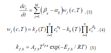
Process of deflagration appearance in hydrogen-air mixes can be treated as transition from slow chemical reactions to fast branching chain reactions. Theory of these reactions was developed by Semenov [6] Equations of chemical reactions can be presented as follows

Where M, n –number of reactions and components of the mix, αij, βij - coefficients of direct and inverse reactions. Arrhenius low is predicted for calculating of speeds of changing of mix components concentration i c :
In present paper gas mix of 9 component: Н2, О2, Н, О, Н2О, ОН, НО2, Н2О2, N2 was treated. For present investigation the next 11 the most widespread reactions where choose: (Table 1)
Table 1: Chemical reactions.

Two algorithms were used for numerical solving of system (7)- (9). The first one was solving of fool system of stiff ODE (7)-(9) on the basis of numerical Gear method. Idea of the second one [5,6] is the next. Deflagration in hydrogen-air gas mix appear as sudden explosion after long period of induction (for more low initial temperature the period of induction is longer). In this induction period concentrations of radicals Н, О and ОН are grows. Mass of radicals, nevertheless stay small and velocity of their changing are negligible, and one radical component transverse to the others. This explosion mechanism is branching chain reaction introduced by Semenov [5]. In this case system of kinetic equations divided into three subsystems. System of two differential equations for concentration of H2 and H2 O2 are solving separately. The concentrations of radicals H, O, OH and HO2 are found from algebraic system with assumption of “quasi stationary” concentration, and for “large unknowns” system of three differential equations is solved after some time steps of solving first and second subsystem with bigger time step.
Numerical simulation of two-dimensional flows of hydrogen-air mixes with deflagration appearance were provided for two configurations of asymmetrical channels.
Flow in Non-Reflecting Nozzle
Axe symmetrical channel with non-reflecting nozzle initially filled with hydrogen-air mix with little amount of water (it involved as collision partner in reaction 5 and 7 of Table 1) with atmosphere meanings of gas dynamics values. At the initial moment shock wave of intensity Msh.w.=1.9 began to move from the right side of the region. During the spreading of shock wave near the top and the bottom bounds of the region deflagration of gas mix appears. On Figure 1 (a)-(d) level lines of temperature (and meanings of its in write column in consequent time moments) are drown. Change of concentration inside the flow demonstrate deflagration appearance. On Figure 1 (e), (f) graphics of concentration of hydrogen (e) and temperature (f) along bottom boundary of the channel in consequent time moments are drown.
Figure 1

Flow in Channel Consist of Combination of Cylinders and Cones
Axe- symmetrical calculation region consist of combination of cylinders and cones. Formulation of the problem is similar to the previous one. Shock wave of intensity Msh.w.=2.7 spreading from the left boundary of the region. Initiation of deflagration appears at the corner boundary point between secondary cone and secondary cylinder. On Figure 2 (a) –(d) level lines of temperature and meanings of temperature (in write column) in consequent time moments are drown. On Figure 2 (e), (f) graphics of temperature (f) and concentration of (e) along bottom boundary of the channel in consequent time moments are drown.
Axial Flow in Channel Between Two Coaxial Cylinders
Calculation region situated between two coaxial cylinders. Formulation of the problem in main is similar to the previous ones. Shock wave of intensity Msh.w.=5. spreading along the cylinders surfaces from the left boundary of the region. Initiation of deflagration appears near outside surface at the beginning of shock spreading and later near upper point of the graphic. On Figure 3 (a) –(d) level lines of temperature and density and meanings of temperature (in write column) in consequent time moments are drown. On Figure 2 (e), (f) graphics of temperature (f) and density (e) along outside bottom boundary of the channel in consequent time moments are drown. This flow in some aspects similar to flow on rotating detonation region.
Figure 2

Figure 3

Algorithm for calculation of deflagration initiation for viscous turbulent flows of hydrogen-air mixes was provided. In--viscid flows were calculated by using pure upwind variant of Chakravarthy-Osher difference scheme This variant of scheme made it possible to avoid oscillations of values of radical’s concentration near points of deflagration appearance. Calculations of viscous turbulent flows in the center of cells were made with using values of supplementary unknowns defined on the border of cells as part of Roe-Pike method of approximation of Riemann problem for in--viscid flows calculations. After those pure upwind meanings of viscous turbulent flows where used. So, in-viscid and viscous flows are calculated from the same meanings of supplementary unknowns. Calculations of two examples of flows with initiation of deflagration in hydrogen-air mixes in two-dimensional channels by this algorithm where provided. For decision of system of kinetic equation two algorithms where used: the first one is decision of fool system of kinetic equation for multistage hydrogen-air reaction, and the second is algorithm based on Semenov’s theory of branching chain reaction. For calculation performing structured curvilinear calculation grids were constructed by author’s algorithm, based on decision of system of PDE equation of parabolic type [7].


