info@biomedres.us
+1 (502) 904-2126
One Westbrook Corporate Center, Suite 300, Westchester, IL 60154, USA
Site Map
Received: April 11, 2018; Published: April 20, 2018
*Corresponding author: Shahrukh Agha, Department of Electrical Engineering, COMSATS Institute of Information Technology, Islamabad, Pakistan
DOI: 10.26717/BJSTR.2018.04.000981
In this work high throughput and low power implementations of two dimensional Discrete Fourier Transform, Discrete Cosine Transform and MPEG Motion Estimation, for battery powered real time applications, using configurable multiprocessors, are proposed and compared in terms of speed, power, area and type of application. The results show the significance of multiprocessing in reducing the computational complexity of the application depending upon the type of application and the speed, area or power constraint.
Keywords: Two-Dimensional Discrete Fourier Transform; Discrete Cosine Transform; Motion Estimation, Multiprocessing; Real Time Processing
Real time computational complexity of Motion Estimation (M.E.) [1].Process in MPEG (Moving Picture Experts Group) [1]. Compression standard corresponding to a frame rate of 25 CIF (Common Interchange Format) (352x288) sized frames per second on a sequential processor involve billions of arithmetic operations and millions of memory accesses [1]. Achieving this throughput, for an ordinary sequential processor, is difficult for two main reasons. One is external memory access delay and second is high power consumption [1]. For battery powered applications low power consumption becomes important especially when the application running has real time constraint. Several VLSI architectures for M.E. have been proposed to mitigate the power consumption while achieving the required throughput [1-9]. In MPEG compression standard, after motion estimation the second most computationally complex part is two-dimensional Discrete Cosine Transformation (DCT) and Inverse Discrete Cosine Transformation [1-5,10-16].
Followed by Variable Length Encoding or Arithmetic Encoding [17]. Similar to motion estimation, various low power and high throughput VLSI architectures of two dimensional DCT (2D DCT) algorithms have been proposed [10-16].Other techniques for achieving the high throughput for M.E. and DCT involve Multiprocessing [2-5,18-19]. and Factorization/SIMD (Single Instruction Multiple Data or Data Level Parallelism) [2-5,18-19]. The benefit of multiprocessing as compared to dedicated VLSI architectures comes in terms of flexibility for different applications possibly at a cost of more area, time and power consumption [1]. Other ways for accelerating M.E. process include use of sub sampling M.E. algorithms at a cost of some reduced visual quality [1-9]. Similarly, fast DCT algorithms [20]. with reduced operations similar to Fast Fourier Transform (FFT) [21]. have been implemented. Similarly Discrete Fourier Transform (DFT) has its applications in the field of signal, image and video processing such as OFDM and M.E. and due to its complexity is considered here as well.
In [22].Multiprocessing of DFT is presented. In[22].Authors have utilized standard platforms and already built hardwires including SIMD architectures and multiprocessors to run the applications while their aim hadbeen to reduce the runtime computational complexity of 1D DFT. In [23]. the authors describe a shared memory multiprocessing system and multistage interconnection-based multiprocessor systems especially for FFT algorithms. A theoretical analysis for the speeding up in the speed of the FFT algorithm (1D and 2D) is presented.In this work we aim to present configurable multiprocessing system for M.E, 2D DCT and 2D DFT The novel aspects of this work are as follows. Developing configurable multiprocessor system with and without caches for 2D DFT, 2D DCT and Motion Estimation by extending the scalar RISC processor architecture and proposing efficient use of the multiprocessors for these applications. The structure of the paper is as follows.Section 2 presents a brief overview of mathematical analysis of M.E., DCT and DFT Section 3 presents the Multiprocessing of 2D DFT, 2D DCT and M.E. Section 4 presents the Results. Section 5 presents the discussion of the results and finally section 6 presents the conclusions.
In block matching M.E., an Nan or 16x16 block (macro block (MB)) of pixels in the current frame is searched in an area (search area) in the reference frame for best match using a matching criteria known as Sum of Absolute Difference (SAD) metric [1-9].
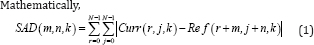
Whereas, (m, n) is the CMV (Candidate Motion Vector) coordinate in the search area [1]. and 'k' is the temporal coordinate. 'Curr' and 'Ref' are current and reference frames respectively. (r, j) are the pixel coordinates relative to the current MB position. The motion vector (MVx, MVy) is the coordinate of CMV with the minimum SAD, i.e.
[MVx, MVy] = arg min SAD(m, n)
Let g1 and g2 be two images of sizes MxN such that g2 is replica of g1 shifted over d=(dx,dy), such that g2(x,y) = g1(x-dx,y-dy), then according to the Fourier shift theorem, their two dimensional discrete fourier transforms are related by,
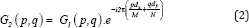
Where G1 and G2 are frequency domain values of 'g1' and 'g2'. 'D' represents the displacement vector, '(p,q)' represents the frequencies and 'i' represents complex quantity iota.
The expression in eq. (2) evaluates Global Motion Estimation[1]. [16].
DCT [23].Is normally used in removing spatial redundancy and can be considered as real part of a typical form of Discrete Fourier Transform (DFT) [24-26].Mathematically 1D DCT is given by,
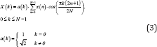
Where ‘M’ is equal to ‘N’ in this case. In [14].The 2D DCT is implemented as Transform of Transform using separable property [14]. due to reduced computational complexity. Or in other words the 1D DCT is first applied along the rows of the 2D data matrix ‘E’ and then the 1D DCT is applied along the columns of the resulting matrix.

Where, ‘C’ is matrix of DCT cosine values and ‘CT’ is the transpose of the matrix.
2D Inverse Discrete Cosine Transform (IDCT) [26]. is used as inverse of 2D DCT for reconstructing image in image or video compression algorithms.

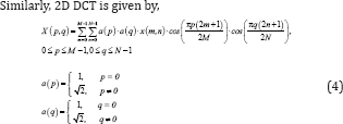
Discrete Fourier Transform is used in frequency analysis of discrete signals. Mathematically, 1D DFT is given by,
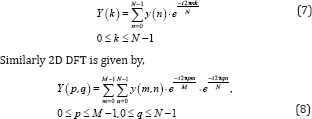
Just as in the case of 2D DCT, 2D DFT can be implemented as Transform of Transform using seperable property [27].i.e.
Y = F . E. FT (9)
Where, ‘F’ is the 2D matrix of complex exponential values and ‘E’ is the data matrix.
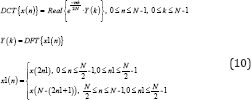
Where 'DCT and 'DFT stands for DCT and DFT operators. 'Real' stands for real value of a complex number.From the above relationship [25]. DCT and DFT can be derived from each other.
In [28].[22]. [29-30]. the multiprocessing of 2D DFT is mentioned. In this work we have defined a shared memory multiprocessing strategy. For this purpose the ISA (Instruction Set Architecture) of a 4 stage pipelined RISC (Reduced Instruction Set Computer) processor [31]. is extended for implementing multiprocessor instructions. Similarly multiprocessing compiler and assembler are implemented. 'MPROC' and 'ENDMPROC' are keywords (or instructions) for enclosing the function which contains loop (for loop) to be unrolled and mapped to the multiprocessors. 'UNROLL' command will be used for initializing the multiprocessors. 'BARRIER' command is used for multiprocessing synchronization [32].
Figure 1: Parallelisation of 2D DFT using Multiprocessing.

(Figure 1) shows multiprocessing instructions for the mapping of the 2D DFT algorithm on the multiprocessors. This is block level parallelization in which each processor core executes 2D DFT of a data block (8x8 or larger size). The program in Figure 1 computes 2D DFT of 8x8 blocks of a QCIF image. The 2D DFT is implemented as DFT of DFT using FFT.
The 1D FFT and hence 2D DFT is implemented as in-place algorithm. 'Function' is a keyword followed by an optional name of a function 'mainl' (in this case).'Re' and 'im' are declared as arrays of size 64 and of type 'floating'. Array 'rel' is declared as array of size 50688 (two QCIF sized frames) to be mapped on the external memory. Variables 'm', 'n' contains values which denote size of FFT. 'dft_h' is a function not shown here which applies FFT algorithm horizontally on each row of the input8x8 data block and then stores the result back to the location of data block. Due to this, extra memory usage is reduced.Function 'transpose' fetches the 1D FFT data and takes its transpose and save the result to the onchip memory (arrays 're', 'im'). The alternative to taking the transpose is to fetch 1D DFT data with a stride (displacement between consecutive memory accesses) equal to the row length of image, then apply FFT and storing the data back to the same locations.
The later way saves the onchip memory. Function 'dft_h1' applies 1D FFT along the rows of the transposed result. Function 'transposer takes the transpose of the result to obtain 2D DFT and saves the result back to the external memory. These all function calls are located inside a 'for' loop containing loop variable 'mp'. This denotes to the compiler that all the instructions inside this loop are to be unrolled and mapped to the corresponding cores (in this case total cores are four). The instruction 'BARRIER' synchronizes all the cores. The instruction 'UNROLL' initiates the multiprocessors. Only main processor (right most processor in Figure 2) executes the 'UNROLL' instruction and upon executing it initiates the rest of the processors. On encountering the 'BARRIER' instruction, the processor stops executing further instructions. When all the processors have executed the 'BARRIER' instruction, the multiprocessing control unit (including AND gate) (Figure 2).Informs the main processor to start executing the next instructions.
The other processors remain stopped until 'UNROLL' instruction is encountered by the main processor which initiates the execution of the rest of the processors. The instruction or keyword 'MPROC' provides necessary information to all the cores and the instruction 'ENDMPROC' terminates the multiprocessing and the instructions following to it will be executed by only the main processor (first of the four processors) until again 'MPROC' instruction is encountered. Each of the processors contains a cache along with a simple cache snooping mechanism [33]. For external memory or slave accesses, the highest priority is given to the first or main processor and so on. In a similar way 2D DFT implemented as DFT of DFT using 1D DFT is mapped on multiprocessors. The other way to parallelize the 2D DFT is to parallelize the inner loop of 2D DFT algorithm, i.e. depending upon the number of processor cores allocated, (1, 2, 4 etc.), each processor core will execute FFT of a corresponding data row and will write the result to the external memory.
Similarly during computation ofVertical DFT, each processor core will execute FFT along the column and will write the corresponding 2D DFT result to the external memory. In Table 1 the numbers of processor cores mentioned for this purpose are 1, 2 and 4. 2D DFT algorithm is implemented as DFT of DFT using the separable property and 1D DFT is implemented as 1D FFT (radix 2).In the same way the external and internal loops of the motion estimation process of MPEG compression, i.e. loop of current macro blocks and loop of candidate motion vectors (CMV) can be mapped to the multiprocessors [2-5]. The difference can be in the requirement of processor’s RAM (storing data and variables) and ROM (storing program). In [2-5].External loop of motion estimation process was parallelized, i.e. parallelizing current macroblocks using multiprocessors.
Table 1: Simulation time/Dynamic Instructional Complexity, Dynamic Power and Chip Area. These results are obtained when 2D DFT, using 1D DFT, of 8x8 data blocks (MB) is implemented (mapped) on multiple processor cores with cache.

Figure 2Shows a symmetric shared memory multiprocessor system. Each RISC processor has a configurable cache, local memory and instruction memory (i.e. the size of these memories can be varied).Similarly the number of processor cores is configurable. The multiprocessing bus control unit is an arbiter (bus multiplexer with controller) and a controller. It allocates address and data busses to the corresponding processor depending upon the priority The main processor (the right most processor in (Figure 2). has the highest priority. The priority algorithm utilized is simple, i.e. highest priority for main processor to lowest for last processor core. In multiprocessing mode when an external memory read or writes request is generated by a processor, the multiprocessing bus control unit generates the necessary control signals (ctrl) for the multiplexers (MUX). The left hand ‘MUX’ selects data from the processor cores where's the right hand ‘MUX’ selects addresses.
Figure 2: A Simple Symmetric Multiprocessing System.

When 'BARRIER' instruction is executed by the processor cores, the corresponding processor cores generate a 'Barr' signal (Figure 2). and stops executing further instructions.When all the processor cores have executed the 'BARRIER' instruction, the multiprocessing bus control unit activates the 'sync' line and tells the main processor to execute the succeeding instructions. Similarly on execution of the 'UNROLL' instruction by the main processor, the multiprocessing bus control unit generates the necessary 'ctrl2' signals for the other processor cores which tells the processor cores (other than the main processor) to start executing. There is a cache snooping mechanism [33] . for multiprocessors with caches so that caches could be updated on cache write. In order to efficiently utilize the temporal locality of M.E. algorithm as well as keeping the simplicity of cache, a direct mapped cache of size 512 locations is implemented[34]. The size of 512 is utilized so that a 16x16 sized reference MB and 16x16 sized current MB could be accommodated in the cache. As a result of it memory misses are reduced by 25%.
Initially a subset of C language is used to write the programs for 2D DFT, 2D DCT and MPEG Motion Estimation[35]. By subset of C language we mean that the language may not contain all the features of the C language but contains the necessary features. Hence the standard program of MPEG Motion Estimation which is written in C language is some modified according to the subset of C language. Initially a single scalar compiler and assembler is implemented using MATLAB [36]. The compiler takes the program (written in subset of C language) and generates an assembly language program. The assembly language program generated is according to the Instruction Set Architecture of the four stage pipelined RISC processor [31]. The compiler maps all the local variables, arrays and pointers, declared inside a function, to the local data RAM of the processor. Similarly arrays declared with a keyword 'ext' before them(Figure 1).Are mapped to the external memory.
The register file of the processor is used to store the intermediate values of the variables while evaluating an instruction, e.g. an instruction of type (a = b*c +d*e + f). In order to compute an instruction, the compiler utilizes the load (LD) and store (ST) instructions to move data between register file and the local data memory. The assembler then takes the assembly language and converts it into the binary code for the RISC processor. Similarly this scalar compiler is extended to include multiprocessor instructions, i.e. 'MPROC', 'ENDMPROC', 'UNROLL' and 'BARRIER'. When a function is enclosed by 'MPROC' and 'ENDMPROC', the compiler inserts these instructions at the beginning and end (or at second last instruction position) of the function which provides the processor with the necessary addressing information and tells the compiler that this function will be run on all the processor cores. Similarly 'UNROLL' instruction which is only inserted in the code of main processor tells, upon execution by the main processor, that all the processor cores should start execution.
Similarly 'BARRIER' instruction, which is executed by all the processor cores for the purpose of synchronization, is inserted in the code of the processor cores. Similarly 'ENDMPROC' instruction tells about the end of the multiprocessing, i.e. only main processor will be executing instructions, until again 'MPROC' or 'UNROLL' is encountered. When the 'for' loop containing the 'mp' loop variable is encountered by the multiprocessing compiler, the compiler unrolls all the code which lies within the braces '{ }' of this 'for' loop and generates assembly code for each processor core accordingly. The multiprocessing compiler generates number of assembly language programs equal to the number of processor cores. Similarly, the multiprocessing assembler, which is obtained by modifying the scalar assembler, generates binary code in the form of ROM file to be attached with each processor core.
The 'main' function in the program is the only program which is run by only the main processor core. Initially only the main processor runs. Upon encountering the 'UNROLL' instruction the multiprocessing starts.The above mentioned multiprocessing based system is implemented on Xilinx Spartan 3 FPGA XC3S2000 [34] . using VHDL. The synthesis options in Xilinx synthesis tools are adjusted such that the logic designs/architectures are mapped to the LUTs and registers and no other onchip resource of FPGA is utilized. This leads to better area comparison. In order to determine the runtime computational complexity of the serial 2D DFT (using 1D DFT/FFT), 2D DCT and motion estimation algorithm as well as their computational complexity when they are mapped on the Multiprocessor architecture, C language [35]. like compilers with multiprocessor instructions are implemented. Similarly corresponding simulators have been implemented.
(Tables 1-9).Shows results of Simulation time/ Dynamic Instructional Complexity, Dynamic Power and Chip Area. These results correspond to the mapping of different loops ('for' loops here) of 2D DFT, 2D DCT and M.E. on multiprocessor cores. Table 1 shows results of Simulation time/ Dynamic Instructional Complexity, Dynamic Power and Chip Area. By simulation time is meant the time taken to complete a task or process. These results are obtained when 2D DFT, using 1D DFT, of 8x8 data blocks (MB) is implemented (mapped) on multiple processor cores with cache, i.e. 2D DFT of multiple data blocks is mapped on multiple processor cores. Similarly(Table 2). shows these results obtained when multiple rows of 8x8 2D DFT, using 1D FFT, is implemented on multiple processor cores without cache. Table 3 shows these results obtained when 2D DFT, using 1D FFT, of 8x8 data blocks (MB) is implemented on multiple processor cores without cache.
Table 2: Results: Simulation time/ Dynamic Instructional Complexity, Dynamic Power and Chip Area. These results are obtained when multiple rows of 8x8 2D DFT, using 1D FFT, is implemented on multiple processor cores without cache.

Table 3: Results: Simulation time/ Dynamic Instructional Complexity, Dynamic Power and Chip Area. These results are obtained when 2D DFT, using 1D FFT, of 8x8 data blocks (MB) is implemented on multiple processor cores without cache.

Table 4: Results: Simulation time/ Dynamic Instructional Complexity, Dynamic Power and Chip Area. These results are obtained when 2D DFT, using 1D FFT, of 8x8 data blocks (MB) is implemented on multiple processor cores with cache.

Table 5: Results: Simulation time/ Dynamic Instructional Complexity, Dynamic Power and Chip Area. These results are obtained when 2D DCT, using 1D DCT, of 8x8 data blocks (MB) is implemented on multiple processor cores with cache.

Table 6: Results: Simulation time/ Dynamic Instructional Complexity, Dynamic Power and Chip Area. These results are obtained when multiple rows of 8x8 2D DCT, using 1D FFT, is implemented on multiple processor cores without cache.

(Table 4).Shows these results obtained when 2D DFT, using 1D FFT, of 8x8 data blocks (MB) is implemented on multiple processor cores with cache. (Table 5).Shows these results obtained when 2D DCT, using 1D DCT, of 8x8 data blocks (MB) is implemented (mapped) on multiple processor cores with cache.(Table 6). shows these results obtained when multiple rows of 8x8 2D DCT, using 1D FFT, is implemented on multiple processor cores without cache. (Table 7).Shows these results obtained when 2D DCT, using 1D FFT, of 8x8 data blocks (MB) is implemented on multiple processor cores without cache. Table 8 shows these results obtained when 2D DCT, using 1D FFT, of 8x8 data blocks (MB) is implemented on multiple processor cores with cache. Table 9 shows these results obtained when external loop of M.E. is implemented (mapped) on multiple processor cores with cache.
Table 7: Results: Simulation time/ Dynamic Instructional Complexity, Dynamic Power and Chip Area. These results are obtained when 2D DCT, using 1D FFT, of 8x8 data blocks (MB) is implemented on multiple processor cores without cache.

Table 8: Results: Simulation time/ Dynamic Instructional Complexity, Dynamic Power and Chip Area. These results are obtained when 2D DCT, using 1D FFT, of 8x8 data blocks (MB) is implemented on multiple processor cores with cache.

Table 9: Results: Simulation time/ Dynamic Instructional Complexity, Dynamic Power and Chip Area. These results are obtained when M.E. is implemented on multiple processor cores with cache.

In (Tables 1-9).The area of design is mentioned as total number of slice Flip Flop registers and 4-input LUTs. The computational complexity here is mentioned in terms of time taken to complete a task (e.g. 2D DCT or M.E) instead of MIPS (Million Instructions per Second) as there are few instructions in the ISA which require more than one clock cycle e.g. branch instructions when they are taken. The maximum achievable frequency of the designs, in FPGA, is upto 45 MHz. Although efficient pipelining techniques can be utilized, while maintaining the efficiency of pipelined processor, to increase the frequency of operation. Dynamic power consumption at a frequency of 25MHz is mentioned. Since all the designs are implemented targeting the same FPGA hence all designs have same static power consumption which equals 184.5 mW. Static power here is the device and design's static (quiescent) power consumption. The dynamic and static power consumption are measured using 'power' utility of Xilinx synthesis tools.
Dynamic power here consists of power (switching power) due to clock, Inputs, Outputs, Logic and Signals (interconnects) [34]. The core supply voltage has value of 1.2V, whereas voltage supply for input/output blocks has value of 2.5 V. In addition, RAM and ROM sizes required by the processor in each case of processor coprocessor combination are mentioned. The results in Tables 1-9 are obtained with processor cores with and without caches as mentioned. For simple and efficient cache system, direct mapped cache with size 512x32 bits is utilized with each processor. In the same way external and internal loops of motion estimation algorithm are mapped to these processor cores. The number of processor cores is then increased to meet the real time constraint for M.E. (e.g. 25 QCIF frames per sec.)Figure 3 shows the complexity or simulation time results from (Table 1). It shows the variation of simulation time with the number of processor cores. Figure 4 shows dynamic power consumption variation with processor cores results from (Table 1) and(Figure 5).Shows processor core area variation with the number of processor cores results from(Table 1).
Figure 3: Variation of simulation time with processor cores.

Figure 4: Variation of dynamic power with processor core.

Figure 5: Variation of core area with processor cores.

(Tables 1-9) shows reduction in the computational complexity of 2D DFT, 2D DCT and M.E. running on a single processor core by using multiple processor cores. Also the use of FFT algorithm further reduces the computational complexity of multiprocessing approach. The same conclusion is drawn from the multiprocessing of 2D DCT. Figure 3 also shows reduction in complexity of 2D DFT, using 1D DFT, due to multiple cores with cache. E.g. the complexity reduces by almost a factor of four when the data blocks are allocated to the four processor cores.Similarly dynamic power consumption and area utilized by the processor cores is mentioned in Tables 1-9and Figure 4 shows increase in dynamic power consumption with the increase in processor cores results from (Table 1) and (Figure 5).Shows increase in area with the increase in processor cores.Through a simple analysis it was concluded that use of a direct mapped cache, of size 512x32b, with the single processor core, in case of M.E. process, reduces the memory miss rate by 25%. This in turn reduces the output dynamic power consumption [34].
On the other hand use of cache also increases area which in turn increases dynamic power consumption due to clock, logic, input and signals [34]. As is mentioned in (Table 4). (For example), the overall dynamic power consumption rises with the use of cache. Other benefits of the use of cache in shared memory multiprocessing system is the improvement in processing speed as there may be less contention for the external data access.In the implementation of 2D DFT/ 2D DCT, two kind of parallelization's are utilized, i.e. one in which a loop which applies 1D DFT/FFT on the rows of data block is parallelized or unrolled and mapped to multiprocessors. The result of this parallelization is shown in Tables 2&6. In this parallelization, the onchip memory (local memory of processor) utilized is, in addition to other variables, equal to the length of one data row for real values and one data row for imaginary values. Initially after reading one row data from external memory into the onchip memory the 1D DFT/FFT is applied and result is written back to the external memory.
Similarly 1D DFT/FFT is then applied along the columns of the result of 1D DFT (which is stored in external memory) so as to compute 2D DFT and the result is written back to external memory. The result of this parallelization is shown in Tables 2-6. The second way of parallelization involves parallelizing the loop which applies the whole 2D DFT on the different data blocks (or macroblocks (MB)). In this parallelization an onchip memory (local memory of processor) equal to the length of a datablock is utilized, one memory block for real values and one memory block for imaginary values as shown in (Figure 1). Due to more onchip memory utilized the area and power consumption results of this parallelization are greater than the previous above mentioned parallelization while having almost the same throughput (speed). It is evident (e.g. from (Tables 2&3). from the comparison of multiprocessing or allocating different data rows to different processors (Table 2). versus different data blocks to different processors (Table 3), that the former parallelization is more efficient in terms of area and power at almost the same throughput.
One reason for this conclusion is the possible reduction in the RAM (local data memory of processor) and ROM size of the processor core due to the use of reduced instruction and data space. Results from Tables 1-9 also show that for the same throughput, multiprocessing approach is more power efficient for 2D DFT and 2D DCT than the single processor at the cost of more area. Similar conclusions are derived for 2D DCT and M.E. from Tables 1-9.For processor-based implementation, the real time requirement (12 to 25 QCIF frames per sec.) of both applications i.e. 2D DCT and M.E. (in MPEG compression) running on a sequential processor requires time of 5140x12 + 4x2.3x99x12 = 72610 ms. Using multiprocessors this leads to approximately 70 to 80 processor cores with caches which have throughput of 151 ms (for one QCIF frame) at 25 MHz, area of 504770 and power consumption of 1267 mW. Although in terms of product of speed, area and power (Tables 1-9).
The most optimized architecture is the single processor core (i.e. having least value of the product) however there are instances when clock speed (e.g. in FPGA) cannot be further improved or increased for higher throughput. In such instances parallelization using multiprocessors become significant.If this design of multiprocessors is carried out using efficient CMOS cells, pseudo- NMOS transistors, pass transistors or efficient sequential registers based on these cells [37]. it can lead to less dynamic and static power consumption and area consumed. The overall conclusion is that use of multiprocessing reduces dynamic computational complexity and possibly power consumption at a cost of more area. The area can be further reduced by mapping reduced portions of programs on the multiprocessor cores. This leads to reduction in power consumption at the same throughput.
When there are multiple applications which run one after another, e.g. in MPEG compression, first stage is preprocessing, then Motion estimation, then DCT followed by Variable Length Encoding or Arithmetic Encoding and IDCT in motion compensation stage etc., multiprocessing system is beneficial in utilizing its reconfigurability and reducing the computational complexity and/ or power consumption. Shared memory multiprocessing can suffer from a limitation in performance due to resource contention which arises when large numbers of multiprocessors are involved [19]. as is evident from the results that the linearity in complexity reduction due to multiprocessors decreases with increase in number of processor cores. It is also important to mention that the above mentioned Multiprocessing system is equally applicable to Inverse DCT and Inverse DFT so as to form an overall real time video or image processing application.
In this work Shared Memory Multiprocessing is considered for implementing high throughput 2D DFT, 2D DCT and Motion Estimation. In [29]. the authors describe a shared memory multiprocessing system and multistage interconnection based multiprocessor systems especially for FFT algorithms. A theoretical analysis for the speeding up in the speed ofthe FFT algorithm (1D and 2D) is presented. In this work implementation of multiprocessing system is presented. Multiprocessing approaches also appears beneficial in terms of power as compared to single processor at the same throughput at a cost of more area e.g. running multiple processors at low frequency is power efficient, in case of 2D DFT and 2D DCT, as compared to single processor at higher frequency. We have also shown that different ways of parallelization's or mapping can have different results of area, power and throughput. The overall conclusion is that use of multiprocessing reduces dynamic computational complexity and possibly power consumption at a cost of more area.
The area can be further reduced by mapping reduced portions of programs on the multiprocessor cores. This leads to reduction in power consumption at the same throughput. There are instances when clock speed (e.g. in FPGA) cannot be further improved or increased for higher throughput. In such instances parallelization using multiprocessors become significant. If this design of multiprocessors is carried out using efficient CMOS cells, pseudo- NMOS transistors, pass transistors or efficient sequential registers based on these cells, it can lead to less dynamic and static power consumption and area consumed.
With increase in number of processor cores the contention due to external memory or shared memory access also increases which can lead to increase in processing time. However this increased processing time can be reduced by using caches if there exists correlation (spatial or temporal) among the data, e.g. in motion estimation. The number of processor cores can be chosen depending upon the constraints of speed, power and area and the type of application. In the future work we shall investigate the effect of Instruction level parallelism and Network on Chip approach in addition to the above mentioned approaches.


