Impact Factor : 0.548
- NLM ID: 101723284
- OCoLC: 999826537
- LCCN: 2017202541
Lozano Carrascal N, Rodríguez Bauzá R and Salomó Collo*
Received: February 26, 2018; Published: March 09, 2018
*Corresponding author: Oscar somo Salomó, Assistant Professor of the International Master in Oral Surgery (IMOS). International University of Catalonia (UIC), Barcelona, Spain
DOI: 10.26717/BJSTR.2018.03.000836
Implant restorations for partially or totally edentulous patients have become a highly predictable treatment, however restoration success is not based only on implant osseointegration whether the aesthetic result [1,2].
Implants ideal 3D position and inclination are mandatory to obtain optimal aesthetic outcomes with long-term stability [3,4]. It's essential to design and manufacture structures and individualized abutments that mimic natural teeth and adapt to the characteristics of each patient providing the necessary support to the peri-implant tissues [5]. A defective restoration due to lack of adjustment, can lead to mechanical or biological complications or even the failure of the restoration and the implant, compromising the long-term functional and aesthetical outcomes. Main advantages of digital work-flow in oral implantology are: Implant 3D planning with the possibility of printing a surgical stent to optimize implant position, changing conventional impressions by digital impressions reducing the dimensional variations and obtaining a printed model, the possibility of designing 3D abutments that allow to support soft-tissue around implant and finally manufacturing all- ceramic restorations with milled-ceramics [5]. The objective of this publication is to show the wide variety of possibilities that digital work-flow offer in oral implantology through the explanation of a case report.
Patient of 28 years attended to the Department of Oral Implantology of the Universitat Internacional de Catalunya because of mobility in 2.1. After a head-trauma. After clinical and radiological examination through periapical X-ray and CBCT (Cone Beam Computered Tomography) scan non-restorable root fracture of tooth 2.1 was diagnosed (Figure 1). Due to the high aesthetic demands and the thin buccal plate, it was decided to perform the atraumatic extraction of the 2.1 and to performed a ridge preservation of the alveolus to place a single implant after the healing period. Atraumatic extraction of tooth 2.1 was carried out and the alveolus was preserved following the Ice-Cone technique described by Elian et al. [6], using a collagen membrane (Bio-guide®, Geistlich Biomaterials, Parma, USA) and Xenograft (Bio-Oss, Geistlich Biomaterials, Parma, USA), later on membrane exposure was covered with soft tissue graft obtained from the palate fixed with single sutures and finally provisionalized with Maryland bridge (Figure 2).
Figure 1: Initial Situation of 28-Year Old Woman, with High Smile Line and Non-Restorable Root Fracture of 2.1: (a) Frontal View; (b) Periapical Radiograph at Baseline; (c) Axial Slice of the Cone Beam Computered Tomography Scan.

Figure 2: Frontal View after Tooth Extraction with the Provisional Maryland Bridge.
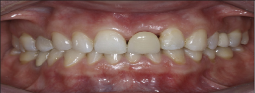
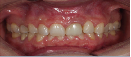
After 6 months healing impressions were taken to confection a diagnostic wax-up, and then a radiological splint. After the CBCT Scan, implant planning was performed with MGuide® Software (MIS Implants Technologies, Israel) (Figure 3). Under local anesthesia a 4 per 10 mm. Astra TX® implant (Astra Tech®, Densply, Sweden) was placed, due to the poor availability of bone an implant dehiscence was created in the buccal area, simultaneous bone regeneration was performed with Xenograft (Bio-Oss®, Geistlich Biomaterials, Parma, USA) and membrane (Mem-Lok®, Bihorizons, Birmingham, USA) [7]. As high implant primary stability was not achieved patient continued with the Maryland Bridge during the healing period (Figure 4). Six months after implant placement, a connective tissue graft harvested from tuberosity was performed to improve soft tissue contour around implant. An atraumatic second surgery [8] was performed using the provisional Maryland Bridge that the patient wears during healing period by the progressive addition of filling material.
Figure 3: Clinical Situation 6 Months after the Socket Preservation: (a) Frontal View; (b) Lateral View; (c) Occlusal View.

Figure 4: Computer-Assisted Implant Planning of 21 Performed with Mguide® Software.

When implant shoulder was reach a screwed-retained temporary provisional was made with a titanium abutment and composite crown, temporary restoration was modified until the desired emergence profile was achieved. For the definitive restoration, a digital intraoral impression scanner LAVA C.O.S (3M ESPE, Spain) with scanning-abutment Core Scanbody (Avinent®- CORE 3D, Spain) was performed. This system required that the impression surfaces must be isolated from fluids and dusted with a light coating of titanium dioxide powder. Powder point's help to interrelating the video images captured by the sensors, with these images a high-quality 3D surface at real time are generated. While the images are captured, a digital model is obtained in the virtual screen of the scanner. The scan of the 2.1 area was performed, followed by the scan of neighboring teeth or working arch, opposite arch and finally the scan of the bite was carried out (Figure 5). Once the images of the digital impression were inspected and approved, were transmitted electronically to the online laboratory in "STL" format. The design of a zirconia abutment with a titanium interface was performed by the software of CAD design of 3Shape (3Shape®, Denmark), files were sent to the milling center (Avinent®, Spain), for the milling of the structure on the one hand, and on the other, the prototype model or milled model was printed with an 3D Eden 260V (Sistemas Objet, Israel) printer, utilizing a composite injection technique. The restoration material for the crown was IPS E-Max Ceram® (Ivoclar Vivadent AG, Liechtensstein) (Figures 6-9).
Figure 5: (a) Occlusal View of the Crest Before the Implant Placement Surgery; (c) Surgical Stent for the Three-Dimensional (3d) Implant Placement; (c) Situation Of The Implant After Correct 3d Position; (d-e) Contour Augmentation with Desproteinized Bovine Bone Mineral And Covered with a Resorbable Collagen Membrane; (f) The Surgery was Completed by Tension-Free Primary Wound Closure.
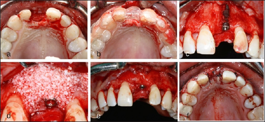
Figure 6: Soft Tissue Management: (a) Frontal View with Implant-Screw Provisional Restoration; (b) Frontal View if the Emergence Profile; (c) Occlusal View of the Emergence Profile.

Figure 7: Digital File "Stl" Obtained from the Digital Intraoral Impression.
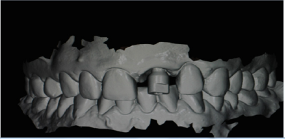
Figure 8: Zirconia Abutment with a Titanium Interface Designed by Cad Software.
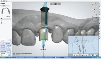
Figure 9: Frontal View at 1-Year Follow-Up.
