Impact Factor : 0.548
- NLM ID: 101723284
- OCoLC: 999826537
- LCCN: 2017202541
Gurkan Karakas1, Woo Jong Shin2 and Kyoshik Park*3
Received: January 17, 2018 Published: January 29, 2018
Corresponding author: Kyoshik Park, Chemical Engineering Department, Myongji University, Myongji-ro 116, Yongin-si, Gyeonggi-do, Korea
DOI: 10.26717/BJSTR.2018.02.000698
Layer of protection analysis (LOPA) was conducted on toxic and flammable hazard of sterilization process using ethylene oxide. Hazard associated with the process were studied using HAZOP and scenarios were developed by applying the HAZOP result. For each scenario, independent protection layers (IPLs) were identified and their frequencies were estimated. Three additional IPLs were considered such as personal protection equipment, monitoring device, and ventilation window. By adding such IPLs, the risk was estimated to be reduced to less than chances per million.
Keywords: Layer of protection analysis (LOPA); Sterilization Process; Ethylene Oxide; Independent Protection Layer (IPL); Risk
Abbreviations: LOPA: Layer of protection analysis; IPL: Independent Protection Layer; EO: Ethylene Oxide; FDA: Food and Drug Administration; PSM: Process Safety Management; HAP: Hazardous Air Pollutant; CAA: Clean Air Act; CNS: Central Nervous System; NIOSH: National Institute for Occupational Safety and Health; IARC: International Agency for Research on Cancer; OSHA: Occupational Safety and Health Administration; PEL: Permissible Exposure Limit; STEL: Short-Term Exposure Limit; PPE: Personal Protection Equipment; KETEP: Korea Institute of Energy Technology Evaluation and Planning; MOTIE: Ministry of Trade, Industry & Energy
Ethylene oxide (EO) has been widely used as a low-temperature sterilant since the 1950s. It has been the most commonly used process for sterilizing temperature-and moisture-sensitive medical devices and supplies in healthcare institutions in the United States. EO kills microbes by disrupting life-sustaining molecules.Commercially sterilized medical products must meet stringent U.S. Food and Drug Administration (FDA) safety regulations that address product sterility (i.e., microbial levels) and acceptable levels of EO residue. Analytical techniques are used to identify, assess and address risks within the pharmaceutical industry such as HAZOP together with complementary quantitative method [1].In order to guarantee the safety of pharmaceutical product, some kinds of risk analysis and risk assessment is studied recently [2].HAZOP analysis is a process hazard analysis method that has been widely applied to the chemical processing industries including EO plant [3].
EO is a hazardous chemical and is both flammable and toxic, listed in 29 CFR 1910.1047in the USA regulation. It is classified as highly hazardous chemicals in the Process Safety Management (PSM) and Hazardous Air Pollutant (HAP) in regulations under the Clean Air Act (CAA). The flammable range of EO/air mixtures is 2.6 -100%under ambient conditions and its flames can accelerate very rapidly [4-6]. It is difficult to design and install reliable explosion control systems, particularly when adding EO to existing process equipment. In order to avoid explosions, facilities must maintain lower EO concentrations entering furnaces below the LFL. National Fire Protection Association (NFPA) codes require facilities to dilute EO concentrations transported to furnaces to less than 25% of the LEL, or 6,500ppm [7]. A typical chamber concentration during sterilization is generally applied between 220,000 and 440,000ppm (400-800 mg/L), which is a very explosive concentration. The acute (short-term) effects of EO to humans is as follows; central nervous system (CNS) depression, irritation of the eyes, and mucous membranes.
The chronic (long-term) exposure may cause irritation of the eyes, skin, and mucous membranesand problems in the functioning of the brain and nerves [8]. A study conducted by the National Institute for Occupational Safety and Health (NIOSH)showed that long term exposures to EO increases the risk of bone cancer in men and breast cancer among women [9]. EPA has classified ethylene oxide as a probable human carcinogen. International Agency for Research on Cancer (IARC), a part of the World Health Organization, classifies EO as a Group 1 human carcinogen (sufficient evidence of a cause and effect relationship between exposure to the material and cancer in humans). The Occupational Safety and Health Administration (OSHA) of the USA defines permissible exposure limit (PEL) is 1ppm, averaged over an 8-hour workday and shortterm exposure limit (STEL) must not exceed 5ppm for 15minutes [10]. In addition, employers are required to take certain actions (e.g., conduct medical surveillance and periodically monitor worker exposures) when employee exposures exceed 0.5ppm averaged over an 8-hour workday.
Evaluating hazard and assessing risk of hazardous facilities are one of the most important activities to keep the site safe. Several studies have been conducted such as on how to review the current methodologies for plant layout optimization and to resolve facility siting issues [11], on how to reduce accidental exposure to various regents that are toxic, explosive, or carcinogenic [12], or on how to apply on an advanced layers of protection analysis (LOPA) method to assess the risk of a chemical process [13]. The layer of protection analysis (LOPA) was introduced in the 1990s as a method for semi- quantitative risk assessment, having advantages of both qualitative and quantitative method of risk evaluation as has been described in the CCPS textbook [14]. LOPA is known to be a powerful analytical tool for assessing the adequacy of protection layers used to mitigate process risk.
Because of the variability of products, packaging, load density, etc., each product type (e.g., tubing, catheters, containers, syringes, bandages) requires a unique treatment cycle to ensure sterilization. Figure 1 shows general process of sterilization using ethylene oxide. Cycle variables include EO concentration, duration of exposure, temperature, and humidity, vacuum applied during sterilization, and inerting and gas washing cycles required removing oxygen and residual EO respectively. In the studied case, the ethylene oxide sterilization system comprised of 3m3sterilization chamber equipped with external heating jacket, access door, vacuum system, and humidification system, nitrogen inserting system, EO gas delivery system, exhaust system and ethylene oxide removal system. The equipments are located in separate containment areas equipped with ventilation (Figure 1).
Figure 1: General process of sterilization using ethylene oxide.

Figure 2: Sterilization System Layout: 1. Sterilization chamber; 2. Sterilization chamber access door; 3. Ventilation system; 4. Hot water system; 5. Steam generator; 6. Liquid ring vacuum pump; 7. Water separator; 8. Reactor-stripper circulation pump; 9. Reactor heater; 10. Control system and monitor; 11. Ethylene oxide cylinder (2 pc) and digital balance; 12. Nitrogen cylinders (2 pc); 13. Stripper-hydrolysis reactor; 14. Ventilations grills (3 pc); 15. Ventilation exhaust.
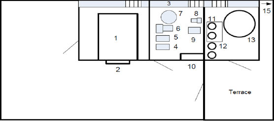
The layout of sterilization department applied to this study is shown in Figure 2.The sterilizer is isolated from the other sections of the production facility. The system is located on the top floor of 3 story building. The confinement, which stores EO, N2cylinders [11,12] and splitter-reactor [13] are located in terrace section out of the building. Three sections of sterilizer are separated by wall and all three sections have separate locked doors against unauthorized access. The air ventilation system has separate grills [14] and negative pressure is applied by ventilation fan which sucks air from all three sections and exhaust is located outside of the building [15]. The process can be monitored and controlled from outside [10] by graphical user interface and PLC system. In addition, the system log is kept by the printer connected to the system. The process parameters and operational mode can 6 only be changed by authorized person, which is assessed by 5-digit user codes. Calibration and major process parameters can only be tuned by service engineer through higher level access codes (Figure 2).
The sterilization cycle is initiated by two stepvacuum-N2 cycle for inerting. Steam is injected to achieve desired humidity level within the chamber to condition the products and to improve the sterilization effectiveness. EO is charged from pressurized 80 pound cylinders as 10%-90% ethylene oxide in carbon dioxide housed in cabinets located alongside each chamber. Products are exposed to 400-800 mg/l EO concentration while the chamber is maintained at 37-55oC, 30-80% relative humidity for a predetermined period between 2-4 hours called the "dwell" phase. The pressure on dwell phase depends on the concentration of ethylene oxide in gas cylinders and adjusted ethylene oxide concentration within the sterilization chamber.
Figure 3: Sterilization cycles and sequencing.
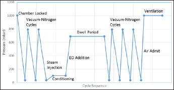
If 90% EO-10% CO2gas mixture is used, the typical dwell phase concentration of 680mg/lis achieved at 600 mbar pressure. Therefore, a positive pressure around 4 bars is applied for 10%EO- 90% CO2gas mixture is used. At the end of this phase, the chamber gas mixture is evacuated to the acid scrubber that removes EO. Approximately 60% of the EO is exhausted from the chamber during this phase of the cycle. The chamber then undergoes a series of nitrogen and/or air washes to remove the remaining EO. Figure 3 illustrates the sterilization cycle sequencing described in this section (Figure 3).
The design intent is safely store, transport of EO gas and safely changes EO cylinders. General recommendations for installing new cylinders are as follows;
a. The cylinders [1-2], vent valves and lines, shut off valves, gas regulators, pressure transducers, transducer cables and sockets, pneumatic valves, line heaters and pneumatic tubings- connectors should be labeled and numbered and also indicated in the written operating procedure.
b. EO line from cylinders to the sterilizer cabinet should have vent line which is connected to the exhaust ventilation system.
The intent of this system is to transfer EO gas to the sterilizer unit.
The intent of this system is to vaporize EO gas and dose appropriate amount of EO into the sterilizer chamber
The design intent is to sterilize plastic and metal medical products under controlled conditions without any release of gas into working environment.
The residual EO is adsorbed in packed adsorption column and catalytically converted into ethylene glycol before disposed.
EO sterilizer involves the flow of air, nitrogen, steam, condensate and water. Consequences of deviation in these flows are considered in this section. Nitrogen is used for inerting the sterilization system and air is used to break the vacuum. The HAZOP analysis of air and nitrogen flow nodes is also essential. In addition, the steam supply, humidification, and heating the sterilization chamber with hot water are also analyzed.
The equipment room, loading room, utilities room and storage room are ventilated by a dilution ventilation system. Also the vent stream from EO cylinder changing operation is connected into the ventilation system.
The EO gas detector is placed in EO storage room and continuously detects and monitors EO concentration in air.
Table 1: The typical hazards of EO sterilization process.
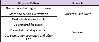
The typical hazards associated with the sterilization process using EO are listed in Table 1. Both workers and employers are recommended to pay attention to prevent overfeeding of the reactor by EO, to store and handle EO properly, and to deal with leaks 11 and spills. The typical hazards for workers and employers are recommended to follows are in the table (Table 1).
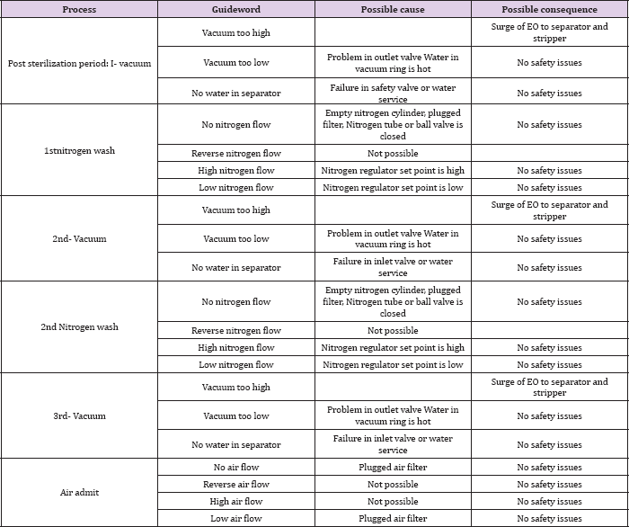
The sterilization process was under HAZOP study to find out hazards of the whole system including sterilization, supplying, storage, and ventilation system (Tables 2-4).
Based on the HAZOP study, the following accident scenarios were developed including overdosing to the reactor, release to loading area, release to equipment area, and leak at storage of EO.
Table 2: HAZOP study EO supply system.
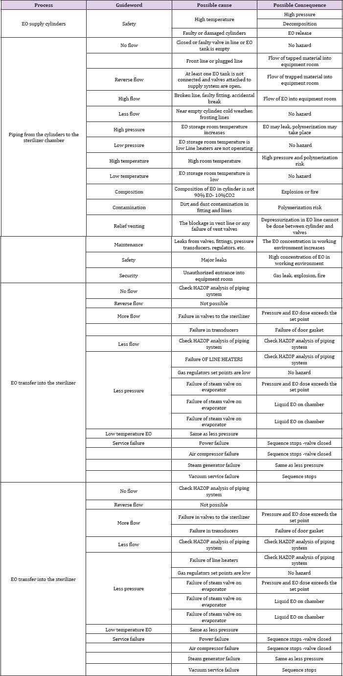
Table 3: HAZOP analysis of EO dosing into the sterilizer.
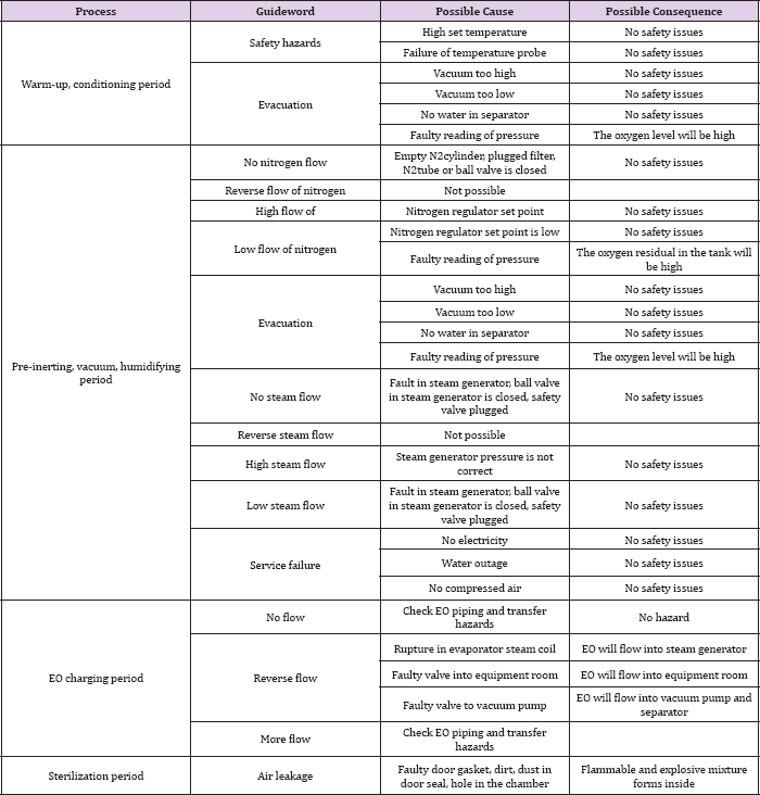
Table 4: HAZOP analysis of post sterilization period.
i. S01: Failure in valves at inlet part→ Failure in pressure transducer →Pressure and EO dose exceeds the set point → Overdosed
ii. S02: Failure in valve at inlet part→ Failure in pressure transducer → Failure of door gasket → Overdosed
i. S11: Small scale leak through sterilizer door gasket → detector malfunction → loading/unloading work exposed to higher than 1.0ppm EO→ workers' exposed probability
ii. S12: Small scale leak through sterilizer door by the process air failure → detector malfunction → loading/unloading work exposed to higher than 1.0ppm EO→ workers' exposed probability
iii. S13: Small scale leak through sterilizer door by the electricity failure → detector malfunction → loading/unloading work exposed to higher than 1.0ppm EO→ workers’ exposed probability
iv. S14: Small scale leak at the equipment area → detector malfunction → equipment area exposed to lower than 6,500ppm (25% of the LEL) → sealing failure between the equipment area and loading/unloading room→ workers' exposed probability
i. S21: Small scale leak by pipeline failure → detector malfunction → equipment area exposed to higher than 6,500ppm (25% of the LEL) → ignition
ii. S22: Small scale leak by compartment failure (gasket, joints, or valve stems) → detector malfunction → equipment area exposed to higher than 6,500ppm (25% of the LEL) → ignition
iii. S23: Small scale leak by reverse flow via air inlet → detector malfunction → equipment area exposed to higher than 6,500ppm (25% of the LEL) → ignition
iv. S24: Small scale leak by pressure switch malfunction → detector malfunction → equipment area exposed to higher than 6,500ppm (25% of the LEL) → ignition
v. S25: Small scale leak by electricity failure → detector malfunction → equipment area exposed to higher than 6, 500ppm (25% of the LEL) → ignition
vi. S26: Small scale leak by air failure → detector malfunction → equipment area exposed to higher than 6,500ppm (25% of the LEL) → ignition
i. S31: Small scale leak by piping → bad ventilation → storage area exposed to higher than 6,500ppm (25% of the LEL) → ignition
ii. S32: Small scale leak by fitting failure → bad ventilation → storage area exposed to higher than 6,500ppm (25% of the LEL) → ignition
iii. S33: Small scale leak by heating pipe line by sunlight → bad ventilation → storage area exposed to higher than 6, 500ppm (25% of the LEL) → ignition
iv. S34: Small scale leak by unintended open of valve → bad ventilation → release of trapped EO→ ignition
The likelihood data are given in Table 5 for the sterilization process (Table 5).
Table 5: Likelihood data for sterilization process using EO Event.
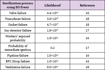
The frequency was determined for each scenario and the results are described below. The frequency ranges from 5.3×10⁻³(f23) to 8.5×10⁻⁶ (f11,f12,f13) are associated with the release to equipment or loading area, ranges from 5.8×10⁻¹⁰(f01) to 6.2×10⁻¹²(f02) associated with overdosing to the reactor, and ranges from 1.5×10⁻⁵(f31, f32, f33) to 6.5×10⁻⁶(f34) associated with leak at the storage.
f0l = (4.4 ×10⁻¹³()(3×10⁻⁴)(4.4 ×10⁻³()(1.0 ×10⁻¹) = 5.8 ×10⁻¹⁰
f0l = (4.4 ×10⁻⁹()(3×10⁻⁴)(4.4 ×10⁻³()(1.0 ×10⁻¹)(1.0 ×10⁻²) = 6.2 × lO-l2
f11 = (4.7 ×10⁻³)(1.8×10⁻¹)=(1.0×10⁻²)= 8.5 ×10⁻⁶
f12 = (4.7 ×10⁻³)(1.8×10⁻¹)=(1.0×10⁻²)= 8.5 ×10⁻⁶
f13 = (4.7 ×10⁻³)(1.8×10⁻¹)=(1.0×10⁻²)= 8.5 ×10⁻⁶
f14 = (1.0×10⁻¹) (1.8×10⁻¹) (1.0×10⁻²) (4.7× l0-3() = 8.5×10⁻⁷
f21 = (1.0×10⁻³) (1.8×10⁻¹)(0.296) = 5.3×10⁻⁵
f22 = (4.7×10⁻³) (1.8×10⁻¹)(0.296) = 2.5×10⁻⁴
f23 = (1.0×10⁻¹) (1.8×10⁻¹)(0.296) = 5.3×10⁻³
f24 = (1.0×10⁻²) (1.8×10⁻¹)(0.296) = -5.3×10⁻⁴
f25 = (1.0×10⁻²) (1.8×10⁻¹)(0.296) = 5.3×10⁻⁴
f26 = (1.0×10⁻²) (1.8×10⁻¹)(0.296) = 5.3×10⁻⁴
f3l = (1.0×10⁻³)(0.5×10-01)(0.296) = l.5 ×l0-5
f32 = (1.0×10⁻³)(0.5×10-01)(0.296) = l.5 ×l0-5
f33 = (1.0×10⁻³)(0.5×10-01)(0.296) = l.5 ×l0-5
f34 = (4.4×10⁻³)(0.5×10-01)(0.296) = 6.5 ×l0-5
Based on the HAZOP study and developed scenario, countermeasures can be obtained to reduce hazards in the sterilization process using EO. Among the developed scenarios, overdosing to the reactor may cause off-specification of the product and is little harmful to workers and facility, and no further analysis is needed. EO release can be very harmful to cause toxic exposure to the workers or became explosive. The EO release to the equipment chamber, loading area, and storage area can intoxicate workers or can be exploded. The scenario associated with the release to loading area has likelihood ranged from 8.5×10⁻⁶ to 8.5×10⁻⁷. The scenario with frequency of 8.5×10⁻⁶ corresponds to either small scale leak through sterilizer door by the process air failure or by the electricity failure followed by loading/unloading work exposed to higher than 1.0ppm EO with detector malfunction [16-18].
If adequate personal protection equipment (PPE) is available together with monitoring system, then the frequency can be improved to the level of 10-6. The scenario associated with the release to equipment area has likelihood ranged from 5.3×10⁻³ to 5.3×10⁻⁵. The scenario with frequency of 5.3×10⁻³corresponds to small scale leak by reverse flow via air inlet followed by equipment area exposed to higher than 6,500ppm (25% of the LEL) with detector malfunction, then ignited. If adequate ventilation windows are added, then the frequency can be improved to the level of 10-6. The scenario associated with the leak at storage area has likelihood ranged from 1.5×10⁻⁵ to 6.5×10⁻⁶. The scenario with frequency of 1.5×10⁻⁵ corresponds to small scale leak by fitting failure followed by storage area exposed to higher than 6,500ppm (25% of the LEL) with bad ventilation, then ignited. If adequate ventilation windows are added, then the frequency can be improved to the level of 10-6.
Risk of per 1million is generally acceptable one. Risk of EO gas release followed by EO intoxication or explosion at loading/ unloading area and equipment area can be reduced by adding PPE (Personal protection equipment, SIL 1, or) and monitoring system (SIL 2, or) together. Risk of EO gas release followed by EO intoxication or explosion at gas storage facility can be reduced by adding ventilation windows of SIL
The authors would like to thank the study is supported by Middle East Technical University in Turkey and by the Korea Institute of Energy Technology Evaluation and Planning(KETEP)


