 Research Article
ABSTRACT
The cytoskeleton is the main cellular component responsible for bearing mechanical
loads and supporting the cell shape in the adherent cells. Number of structures have
been proposed to investigate the behavior of the cytoskeleton which most of them were
based on stretch elements which only stand against tension forces. actin filaments are
rope-shaped filaments that only tolerate tensile forces. However, in biological systems,
microtubules have a vital role in the behavior of living cells. Microtubules, which are
tube-shaped filaments, have evolved to withstand compressive forces. In this way, the
need to have a structure that has tensile and compression elements together for the
better approximation of cell behavior is necessary. Hence, tensegrity structures were
considered as a tool for modelling and understanding the cytoskeleton behavior.
Multiple experiments have proven that the tensegrity model is an appropriate structure
in approximating the cytoskeleton behavior of non-suspension cells.
In this study, we suggested two different tensegrity structures to examine the effect
of the complexities of these structures in response to mechanical stimulus. Both 6 and
12-strut structures were simulated and subjected to theoretical atomic force microscopy
loading through the software ABAQUS. Next, the relation between structure reaction
forces and the amount of deflection, and also cell response to the stiffness change of
the substrate were investigated. After comparing behavior of these two structures, it
was concluded that it is more appropriate to apply a tensegrity model with fewer struts
in stiffer cells’ behavior. The structure behavior in response to changes in substrate
stiffness revealed that six-strut tensegrity is more sensitive to higher substrates stiffness.
Keywords: Cell Mechanics; Tensegrity Structure; Cytoskeleton; Stiffness of Substrate; Finite Element Method (FEM)
Introduction
Most functions of living cells, including cell growth
and differentiation, are related to cell shape deformation.
Transfiguration of cells is dependent on the cytoskeleton behavior
more than any other organelles [1]. In addition to its effect on cell
shape, structure and deformation, the cytoskeleton is the main
factor of transferring mechanical forces through the cell [2,3].
The cytoskeleton is composed of three main strands of the actin,
microtubule and intermediate filaments. Many experiments have
proved that actin and intermediate filaments are under tensile
forces, while microtubules are suitable to withstand compressive
forces [4,5]. To assess the overall behavior of the cytoskeleton,
several computational models like pre-tensioned cable network [6]
and semi-flexible network [7] have been presented. Most of these
models focus only on the tensile elements. One of the computational
models is a tensegrity model in which both of the compressive
elements and tensile elements are involved.
Tensegrity is a self-balancing structure in which non-connected
compact struts (isolated rods) are floating in a continuous elastic
environment. Ingber [6] showed that for a living cell, the struts
resemble the behavior of the microtubules, and the cables represent actin filaments. Each of the cell components has its own specific role
in cell behavior and balance [8]. In tensegrity structure, pretension
in actin filaments can be balanced with focal adhesion, that is why
tensegrity is not a proper structure to consider non-adherent cells.
Because in non-adherent cells there is no focal adhesion to transfer
mechanical stress through the membrane [9]. In this study, only
adherent cells have been considered. Previous studies applied the
structures of different complexities for studying various aspects of
the cells’ mechanical behavior [1,10-12]. Prendergast, et al. [13]
studied tissue response to mechanical stresses, trying to model a
single spread cell adhered to the substrate while influenced by shear
stress. He also used 6-strut tensegrity structure for the purpose of
modelling cytoskeleton and solid parts for the membrane, nucleus
and cytoplasm [13]. Kardas, et al. [14] modelled an osteocyte inside
the lacunae.
The cell structure has involved a different type of cell component
like cytoskeleton, nucleus, and integrin. Three different models
made by fiber elements have been created for presenting actin
network, intermediate filaments connected to the nucleus, and
microtubules which were connected to the centrosome, while a 30
struts tensegrity has been chosen for modeling the nucleus. They
also examined various types of cytoskeleton fibers arrangement
in the cell. Their study showed that random arrangement is more
consistent with experimental observations [14]. The way of
estimating the nucleus by using the tensegrity structure has been
recorded by Ingber [15,16]. another research on tensegrity as
cell cytoskeleton structure is the Bursa and Fuis study [17]. They
presented a FEM model for the eukaryotic cell. Their model involved
tensegrity (cytoskeleton), membrane, cytoplasm, and nucleus. They
simulated 60 peripheral cables and 30 radial cables, which had the
same joint points at the cellular level.
This model is proper to show transition extracellular force to the
fiber part of the cell. De Santis, et al. [18] have used the tensegrity
structure for investigating cell spreading behavior on the substrate.
They used a FEM model of 6-strut tensegrity to find out how the
cell feels the surface stiffness. They applied a tensegrity structure
with a solid membrane, cytoplasm, and nucleus to a spread cell
attached to an elastic substrate. They finally observed that there
is a one-to-one relationship between microtubules’ compression
and the substrate elasticity [18]. To compare the complexity of
the structure, Chen, et al. [19], used 6 and 12-strut to simulate
intracellular force distribution and stored energy in cell spreading.
They noticed that 12-strut tensegrity has more flexibility to spread.
They also showed that during cell spreading, the stored energy in
cables increased but microtubules would limit the cell spreading by
decreasing energy to zero [19]. Several usages of tensegrity have
been found for estimating cellular behavior, but there is a simple
question here. Could the same structure be used for different cell
phenotypes with different stiffness? How should it be dealt with
cell stiffness?
The objective of this study is to assess the role of tensegrity’s
structure complexity on adherent cell behavior cell. A vertical
deflection was applied to the structure to mimic BioMEM system
for measuring cell compliance [20] experiment, and the reaction
forces of the structure to this displacement were assessed. Then, the
reaction force of this structure vs. the substrate stiffness changes
was investigated to study the effect of the substrate stiffness on
cellular behavior.
Methods
Two types of cytoskeletal structures based on spherical
tensegrity with 6 and 12-strut models are proposed. All the vertices
of the tensegrity model are the coupling points of the struts and
cables, and all of them are located on the circumference of a sphere.
The diameter of the sphere is as equal as cell diameter. The 6-strut
tensegrity was produced by three perpendicular hypothetical
planes, all of which pass through the center of the sphere. There
was a pair of parallel struts on each plane located on both sides of
the center of the model, and none of the pairs of struts were parallel
to each other. After adjusting the struts in their positions, the end
of each strut was connected to the end of the nearest adjacent
struts, that is, all the adjacent vertices in the model connected by
cable. This connection was made in a manner where each strut is
surrounded by four cables. Finally, the 6-strut tensegrity structure
was completed by adding 24 cables [21]. The 12-strut tensegrity
is a spherical structure, in which four hypothetical planes are
overlapped only in one point (the central point of the sphere).
In this structure, there are three struts in each hypothetical
plane. The struts are placed together in a triangle-like structure and
the head or end of the strut are connected to the nearest adjacent
vertices through four cables. The 12-strut tensegrity model is
completed by adding 48 cables [21]. In the cytoskeleton, the end
of each microtubule which is close to the membrane is connected
to the integrin. Integrin is a transversal membrane’s proteins that
are contacted to the extracellular environments outside of the cell
and transfer all extracellular interactions into the cell. Inside the
cell, integrin sends the extracellular forces toward the cytoskeleton
and makes the filaments to sense tensile stresses. This initial tensile
force is subjected to microtubules compression and causes a forced
balance in the whole cytoskeleton. This force balance of filamentary
strands eventually leads to balance in the shape and structure of
the cell. In fact, the stability of the tensegrity structure is dependent
on the pretension of cables. In this simulation, pres-tress of 82kPa
for the initial tension of cables and 12.4kPa for compressive prestress
of struts were applied [22].
For substrate, an isotropic elastic solid disk was created. Then,
in order to connect the structure to the substrate, the tensegrity
structure was placed on the substrate in such a way that some of
the struts ends touched the substrate. The cell model structure had
was created using 6 and 12-strut tensegrity, the cell was places on
the substrate so three and four cables were contiguous with the
substrate, respectively (Figure 1).
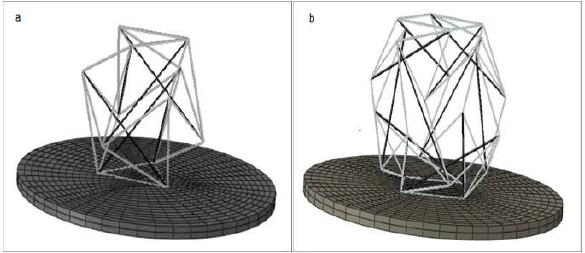
Figure 1: Cell placement on the substrate,
a) 6-strut tensegrity model,
b) 12-strut tensegrity model (elements that are shown in gray and black represent cables and struts, respectively).
Dimensions and Mechanical Properties of Cytoskeleton Components
In the 6-strut tensegrity model, the length of each strut was 14μm, and the distance between two parallel struts was 7μm with a strut cross-section area of 1340 nm2. Young’s modulus and Poisson’s ratio was defined as 1.2GPa and 0.3, respectively [23,24]. Cables are tensile elements with Young’s modulus of 2.6GPa and Poisson’s ratio of 0.3. The cross-sectional area of cables was 570nm2. The substrate was an elastic disk of 1 μm thickness and 30μm diameter. The values of 100 kPa and 0.3 were designated for Young’s modulus and Poisson’s ratio of the substrate, respectively [24].
Loads and Boundary Condition
AFM is a regular and standard experimental method in cell mechanical behavior studies [25]. However, AFM has a sharp point of the contact that may result in the local strain concentration. The alternative method of cell loading using a BioMEM system for measuring cell compliance was suggested [20] that allowed application of the load to the whole upper surface of the cell; thus a similar displacement was applied to all points representing the cell’s upper surface. In order to simulate the BioMEMs load, a downward displacement was applied to the upper vertices of the structure (3 and 4 vertices for 6 and 12-strut tensegrity, respectively). All degrees of freedom for the nodes located at the bottom surface of the disk (substrate) were fixed. In order to attach the tensegrity structure to the substrate, all connected vertices with the disc (located at the end of microtubules) were pinned to the nearest node of the substrate meshes. To study the cytoskeleton behavior, the applied displacement to the upper vertices of the structure (Figure 2) was incremented from 0.1 to 1 μm, and the total reaction force at these nodes was calculated.
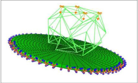
Figure 2: Applied displacement and boundary conditions for the substrate and cell.
Solution
Linear momentum conservation equations (Newton’s second law) is the governing equation of this problem in this study. If σij is the Cauchy stress tensor, the stress form of momentum is presented as Eq. (1):

Here, parameters ρ is the density, b is the body force and a is the linear acceleration. For static condition and avoiding the presence of body forces like weight, Eq. (1) will be modified as:

To solve this differential equation with the FEM, ABAQUS (version 6.4) solver was used [26]. ABAQUS generates a system of equations and solves them by calculating the stiffness matrix and the displacements at any nodes.
Meshing
To model the cables and struts, tension only and compression only truss elements (T3D2) were chosen respectively. For meshing the substrate, the 8-node 3D structural element (C3D8R) was. After the mesh convergence 1824 elements were obtained for the substrate. Nonlinear geometry (Nlgeom) option was checked in step modulus to encounter large deformation problem.
Results
Effect of the Variation of Number of The Strut Elements
The color representation of the stress magnitudes carried by the struts and cables are shown in Figure 3. The effect of the applied prestresses on the elements for both 6 and 12 strut structures are shown in Figures 3a & 3c, while Figures 3b & 3d shows the stress in the structure components when it is deformed by external load. In the prestressed structures, each element is loaded by a prescribed tensile or compressive stress. The uniformity of the elements colors indicates that each member is under either constant tension (cables) or compression (struts). Analysis of the reaction force vs. deformation shows that increased external displacement leads to increases in the reaction force, as one should expect (Figure 4). The obtained data shows that the 6-strut tensegrity model exhibits larger stiffness compared to a 12-strut. Therefore, in order to model behavior of the cell with higher stiffness, application of the 6-struts tensegrity model may be advantageous.
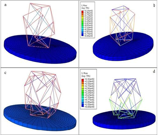
Figure 3: Strut and cable stresses in the 6 and 12-strut tensegrity structures. Pre-stress only
a) for the 6-struts structure and,
b) 6-struts structure and,
c) for the 12-struts structure, external load
d) 12-struts structure.
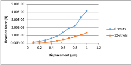
Figure 4: Force-deflection diagram for 6 and 12-strut tensegrity structures.
Effect of the Substrate Stiffness
Substrate stiffness is one of the important factors affecting the
adherent cell in vitro behavior. Depending on their types, cells are
sensitive to a specified range of substrate stiffness. The changes in
substrate stiffness cause changes in cytoskeleton balancing forces
and modifies cell movement along the substrate [18,27]. In order
to evaluate the effect of substrate stiffness on the cytoskeleton,
substrate stiffness was changed from 10 Pa to 100 MPa and the
tensegrity structure’s reaction force was calculated for 1μm
downward displacement. Figure 5 demonstrated the variation of
the reaction force due to the change of the substrate stiffness for
δ=1 μm. Let us define the area where reaction force is sensitive to
the change of the structure’s stiffness as an area of cell sensitivity
to the substrate stiffness. This area has a range of 1 to 100 kPa for
6-strut tensegrity. While 12-strut tensegrity does not depend on
stiffness greater than 1 kPa.
Since the forces of the cytoskeleton are balanced through
substrate stiffness, it can be claimed that the 6-strut tensegrity
compared to 12-strut structure approximates stiffer cells. So,
an increase in the number of struts makes the structure more
flexible and more appropriate to estimate softer cells’ modeling.
The variation of the reaction force along with the stiffness of the
substrate is shown in Figure 6. As demonstrated here, the sensitivity
area is independent of the amount of motility, while reaction force
increases by a rise in displacement. The reaction force changes
against substrate stiffness for the 12-strut structure are shown
in Figure 7. In a 6-strut structure, the response force sensitivity
increases with increasing displacement, while the sensitivity area
is the same and does not change by increasing displacement.
By comparing Figures 5 & 6, it is concluded that in the 6-struts
structures, the variation of the reaction force is greater than that of
the 12-strut structure. This 6-strut tensegrity is more appropriate
for modelling the stiffer cell behavior.
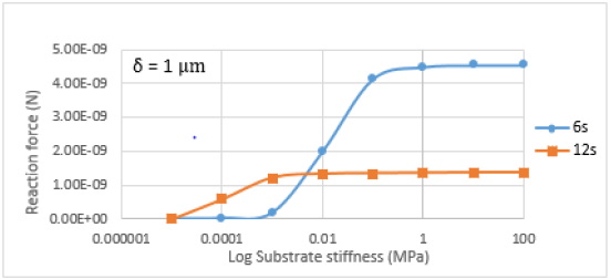
Figure 5: The reaction force vs substrate stiffness for the 6 and 12-strut tensegrity models.
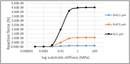
Figure 6: The 6-strut reaction force vs applied displacement.
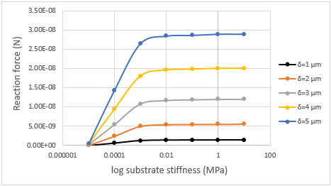
Figure 7: 12-strut reaction Force vssubstrate stiffness in different AFM displacement.
Discussion
Each spherical tensegrity model can be built with the help of a regular polyhedron. Each vertex of the structure is aligned with the polyhedron’s corners located on the surface of the sphere. The obtained results showed that a tensegrity with fewer number of struts creates a stiffer structure. By creating tensegrity structures of the same size, but with increased number of struts, the structure configuration will look more similar to the dome while the length of the struts will decrease, and stiffness of the structure will increase. By reducing the length of the struts, and increasing distance from the center of the sphere, struts have less contribution in tolerating foreign forces, and this makes the structure more flexible. In the area of the cell sensitivity (Figure 5), the balance between cytoskeleton structure and mechanical environment depends on the substrate stiffness. Under the applied external displacement, the shape of the structure will change until the internal forces of the components can withstand the external stimulus. The cytoskeleton attaches to integrin within the membrane by the ends of the microtubules. Hence, integrin could be responsible for microtubule mechanical connection to ECM in biological condition and to the substrate in vitro [28] In vitro conditions the microtubules’ internal forces fluctuate due to the changes in substrate properties. Due to such changes the microtubule internal force will change and, accordingly, the cytoskeleton shape will change to reach another equilibrium configuration.
Statement of Ethics
The study was conducted ethically in accordance with the World Medical Association Declaration of Helsinki. Written informed consent was obtained from the patient for publication of this case report and any accompanying images. A copy of the written consent is available for review by the Editor of this journal.
Conclusion
In this study, two types of tensegrity structure were studied as possible models to approximate the cytoskeleton behavior. Cells were loaded by a uniform displacement applied to the top surface. It is recommended to use a structure with fewer struts to simulate stiffer cell behavior. The cell was attached to the substrate to show in vitro condition. Evaluation of the cell response to alerting substrate mechanical properties (Young’s modulus) showed lower sensitivity range for the structure with more compressive elements. This outcome is compatible with the previous studies and confirms that for simulating softer cells, a tensegrity model with more struts is more suitable.
References
- Coughlin M (1998) A tensegrity model of the cytoskeleton in spread and round cells. Journal of biomechanical engineering 120(6): 770-777.
- Wang N, Naruse K, Stamenović D, Fredberg JJ, Mijailovich SM, et al. (2001) Mechanical behavior in living cells consistent with the tensegrity model. Proceedings of the National Academy of Sciences 98(14): 7765-7770.
- Chicurel ME, Chen CS, Ingber DE (1998) Cellular control lies in the balance of forces. Current opinion in cell biology 10(2): 232-239.
- Ingber DE (2003) Tensegrity I. Cell structure and hierarchical systems biology. Journal of cell science 116(7): 1157-1173.
- DE Ingber (2003) Tensegrity II. How structural networks influence cellular information processing networks. Journal of cell science 116(8): 1397-1408.
- Ingber DE, Dike L, Hansen L, Karp S, LileyL A (1994) Cellular tensegrity: exploring how mechanical changes in the cytoskeleton regulate cell growth, migration, and tissue pattern during morphogenesis. International review of cytology, pp. 173-224.
- Satcher R, Dewey CF, Hartwig JH (1997) Mechanical remodeling of the endothelial surface and actin cytoskeleton induced by fluid flow. Microcirculation 4(4): 439-453.
- Stamenovic D, Mijailovich SM, Tolić Nørrelykke IM, Chen J, N Wang (2002) Cell prestress. II. Contribution of microtubules. American journal of physiology-Cell physiology 282(3): C617-C624.
- Khismatullin DB (2009) The cytoskeleton and deformability of white blood cells. Current topics in membranes 64: 47-111.
- Ingber DE (2008) Tensegrity-based mechanosensing from macro to micro. Progress in biophysics and molecular biology 97(2-3): 163-179.
- Wendling S, Cañadas P, Oddou C, Meunier A (2002) Interrelations between elastic energy and strain in a tensegrity model: contribution to the analysis of the mechanical response in living cells. Computer Methods in Biomechanics & Biomedical Engineering 5(1): 1-6.
- Wendling Mansuy S, Cañadas P, Chabrand P (2003) Toward a generalized tensegrity model describing the mechanical behaviour of the cytoskeleton structure. Computer Methods in Biomechanics and Biomedical Engineering 6(1): 45-52.
- Prendergast PJ (2007) Computational modelling of cell and tissue mechanoresponsiveness. Gravitational and Space Research 20(2)
- Kardas D, Nackenhorst U, Balzani D (2013) Computational model for the cell-mechanical response of the osteocyte cytoskeleton based on self-stabilizing tensegrity structures. Biomechanics and modeling in mechanobiology 12(1): 167-183.
- Ingber DE (1993) Cellular tensegrity: defining new rules of biological design that govern the cytoskeleton. Journal of cell science 104(3): 613-627.
- Ingber DE (1997) Tensegrity: the architectural basis of cellular mechanotransduction. Annual review of physiology 59(1): 575-599.
- Bursa J, Fuis V Finite element simulation of mechanical tests of individual cells. p. 16-19.
- De Santis G, Lennon A, Boschetti F, Verhegghe B, Verdonck P, et al. (2011) How can cells sense the elasticity of a substrate? an analysis using a cell tensegrity model. European cells & materials 22: 202-213.
- Chen TJ, Wu CC, Tang MJ, Huang JS, Su FC (2010) Complexity of the tensegrity structure for dynamic energy and force distribution of cytoskeleton during cell spreading. PloS one 5(12): e14392.
- Zhang Y, Ikehara T, Lu J, Kobayashi T, Ichiki M (2008) Novel MEMS-based thermometer with low power consumption for health-monitoring network application. SPIE, pp. 68001V.
- Kenner H (2003) Geodesic math and how to use it: Univ of California Press
- Barreto S, Clausen CH, Perrault CM, Fletcher DA, Lacroix D (2013) A multi-structural single cell model of force-induced interactions of cytoskeletal components. Biomaterials 34(26): 6119-6126.
- Deguchi S, Ohashi T, Sato M (2006) Tensile properties of single stress fibers isolated from cultured vascular smooth muscle cells. Journal of biomechanics 39(14): 2603-2610.
- Stricker J, Falzone T, Gardel ML (2010) Mechanics of the F-actin cytoskeleton. Journal of biomechanics 43(1): 9-14.
- Ladjal H, Hanus JL, Pillarisetti A, Keefer C, Ferreira A, et al. (2009) Atomic force microscopy-based single-cell indentation: Experimentation and finite element simulation. HAL, pp. 1326-1332.
- Simulia D (2011) ABAQUS 6.11 analysis user's manual. Abaqus 6: 22-2.
- Voloshin A (2016) Modeling cell movement on a substrate with variable rigidity. International Journal of Biomedical Engineering and Science (IJBES) 3(1): 19-36.
- Adam Hacking S, Khademhosseini A (2013) Chapter II.1.3 - Cells and Surfaces in vitro. Biomaterials Science (3rd )., In: B.D Ratner, AS Hoffman, FJ Schoen and JE Lemons (Eds.)., pp. 408-427.
