 Review Article
Introduction
This research is aimed at creating a system of automatic acquisition of three-dimensional data with one or more teeth and oral cavity so as to be able to reconstruct a more accurate substitutive prosthesis. Its purpose is to reduce the disturbance to the patient due to impressions (imprints of teeth, abutments and jaws) and bite registration (imprints of how the teeth and the jaws fit together) and to provide greater precision in the production phase while giving therein a greater reliability in the time. In the classic construction of a dental prosthesis the low accuracy modeling gives an imperfect matching between the prosthesis and the oral cavity which in turn causes lasting disturbance to the patient. Moreover, the creation of a solid model from the impression or mold taken of the patient’s teeth requires contact between the model material and the dental mold and may result in contamination if either is not properly sterilized. Therefore, a non-contact measuring system is essentially required. In order to achieve these results, an automatic system based on a smart sensor with an opto-electronic technology will be realized. All the data will be treated to obtain a model of the tooth adapted for a tool machine. A prototype can be obtained by means of a laser sintering process for the execution of the final prosthesis. An advanced interferometric technique with an automatic image processing system (Holostrain) has been applied.
Dental Measurement Required
The shape of the abutment is frustum conic Figure 1 and the cap, which substitutes the tooth, will be mounted on it using pressure instead of glue. The goal is to obtain the most accurate and reliable reconstruction of the abutment with a precision of 30μ. in accordance with international medical prescriptions. Another important request is that the distance between two contiguous teeth is large enough to guarantee the use of standard sized dental floss.
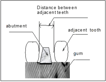
Figure 1: Required measurement.
Projection Moire
The projection moiré technique is based on the projection of
a grating on the object surface and then observed with a different angulation. The depth of the object surface causes a deformation
in the grating in the direction of observation. In this way, the depth
measurement (out of the plane) is transformed in the plane and a
superimposition is applied between the deformed and the reference
grating as shown in Figure 2.
For a more accurate measurement, the “Phase Shifting”
technique in concordance with the moiré technique, has been
applied [1-3]. It is based on the projection of a sinusoidal grating
able to analyze a great quantity of full field continuous data where
the gray level represents the phase values in modulo 2π. The
theoretic scheme (telecentric) regarding both laser and white light
is shown in Figure 3. A grating of pitch p (po in the plane parallel to
the reference plane) is obliquely projected with an incident angle θ
. The grating that has been formed on the object is then observed
in the direction of the angle θ’. The reference grating is projected
on a reference plane and is therewith viewed in the observation
direction. Considering the reference, the intensity in point C of the
reference plane is:
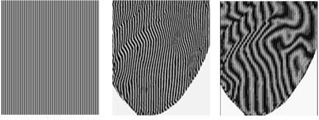
Figure 2: Out of plane profile measurement: a) reference; b) depth deformation; c) superimposition of (a) and (b).
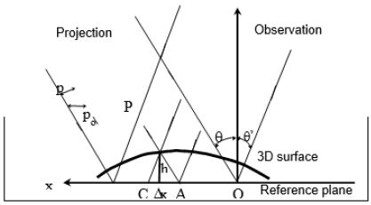
Figure 3: Scheme with collimated light.

Considering point D (object) that is the correspondent point of C and has the same phase of point A, the intensity is:

During the observation, the phase difference between the two images in the same point is:

where:

The height of point D is:

For the particular case of θ’= 0, it is:

In order to obtain a sensitivity of 30μ, assuming po=0,5mm and θ =20°, φCD = 2π/46 is required. Accuracy depends mainly on the precision of the grating and the phase shifter.
Experiment
The experimental tests were conducted using the following
fundamental steps of the Holostrain System by Sciammarella &
Associates:
a) reference phase.
b) reference object.
c) subtraction of the two phases; and
d) depth calculation.
The utilization of a coherent light (laser He-Ne, λ=632,8 hm,
P=30 mW) has allowed us to obtain a sinusoidal grating as required
by the Phase Shifting technique Figure 4. By means of the Twyman-
Green interferometer (that is a variation of the Michelson), the
pitch is given by:

In order to get a pitch of 0.5 mm, it needs:

The post-filter was introduced in order to eliminate the optical noise caused by the beam-splitter. The phase shifting was obtained utilizing a photoelastic compensator (Babinet). The white light set-up Figure 5 allows us to obtain a grid with a higher frequency but with the inconvenience of a lower sinusoidal level than the one produced with the interferometer. An iris diaphragm was positioned in front of the light source to absorb the aberration effects of the different wavelengths. A micrometric translator is also utilized as a phase shifter moving the grating perpendicular to the wave front.
Phase Shifting Technique
The Phase Shifting technique gives a direct way of obtaining the phase and depth of the recorded images. Because the Phase Shifting technique is always affected by random noise, by means of the Holostrain System, it is possible to apply the Fourier Transform technique in order to obtain a digital filtering [4-6].
If the interference equation is considered, there are three unknowns:

The unknowns are the intensity A, the contrast B, and the phase Φ(x) that contains the information to be measured. A minimum of three measurements is therefore necessary to determine the phase. A solution to this problem was found by applying the four-frames Phase Shifting (Holostrain) considering the angles
α = 0°, 90°, 180°, 270°:

Because of the arctangent calculation, the equation (10) is
sufficient only for a modulo π calculation. To determine the phase
modulo 2π, the signs of quantities proportional to sin Φ and cos Φ
must be examined. For this scope the unwrapping technique phase
was applied. We faced the following difficulties in our tests:
a. The existence of deep slopes and swellings.
b. Fringe spatial spacing difficult to filter.
Sensitivity
Considering once again equation (6), the two terms can be
classified as:
1) p0/tanθ - classic sensitivity.
2) φCD/2π - phase difference between the object and the
reference.
The classic sensitivity can be calibrated with an object having a
known depth after having defined the geometrical parameters of the
system. By means of the phase shifting technique an interpolation
up to 1/1000 of the fringes period can be achieved. The sensitivity
gained with the phase shifting technique is therefore much larger
than the geometric measurement.
Errors
Accuracy of Phase Shifting: An error introduced by an
imperfect phase shifting could appear with a sinusoidal oscillation
with a frequency double than the one of the fringes. There are two
approaches to solve these problems:
a) The five-frames phase shifting to compensate the errors
due to the shifter.
The equation (10) becomes:

b) Utilizing a very precise phase shifter as a piezo-electric
transducer that is able to move a mirror linearly over a range of
several micrometers. A high voltage amplifier is used to produce a
linear ramping signal from zero to several hundred volts.
A Babinet compensator was used in our experiments as a shifter.
Its resolution is 1/180 of the fringe periods. The inconveniences
that we found using this instrument were a big distortion of the
grating and a non-uniform shift across the section.
Non-Sinusoidal Gratings: From equation (6) it is possible
to evince that the phase shifting technique is based on utilizing a
grating with a sinusoidal profile. Considering the white light setup,
the grating is generally photographed. Even in the coherent
light set-up, if the components do not have sufficient optical and
geometric qualities, the profile will not be perfectly sinusoidal.
A non-sinusoidal profile, in addition to its evident error in the
measurement, also causes great difficulties for the determination
phase:
a. During the unwrapping technique, the phase range < 2π,
causes problems in defining the fringe order in the local zones.
b. In the presence of discontinuities, deep slopes, bumps,
etc. after the unwrapping, these geometrical surface characteristics
are lost in the final results if smoothing is required.
Solutions to these problems are:
I. Small pitch of the grating.
II. High quality optical components.
III. Blurring of the grating to make it similar to a sinusoidal grating
(photographed grating);
IV. Increase of the shifting step.
Calibration of the System
To evaluate the errors previously discussed, it is necessary to
calibrate the relevant factors for a chosen system [7]. Taking a look
once again at equation (6), it is possible to hi-light the following
steps:
a) Calibration of the classical sensitivity of the optical system.
b) Relation between the depth and the phase h -φ;
c) Calibration of the phase shifter using a reference plane.
d) Calibration of the phase accuracy regarding a specific object
as step (3).
e) Quality of the analyzing object surface.
Preliminary Results
In this preliminary study two different tests were applied in
order to show the principal characteristics:
a. Collimated projection with coherent light
b. Collimated projection with white light.
The measurements were taken on a professional mold and the
abutment was obtained by milling a broken tooth Figure 6. For
the case of coherent light, a grating with a pitch p (=0,5 mm) was
projected on the upper part of the abutment with an incident angle
of 20°. The classical sensitivity is:

To obtain the required sensitivity of 30 μ we must have:

This value means that the errors caused by the phase shifter and by an imperfect sinusoidal grating must be inside the 1/49 of the grating period. The phase shifter accuracy must be Figure 7:

In the case of white light, a grating with a pitch p (=0,1 mm) was projected with an incident angle of 20°.
The classic sensitivity is:

For the requested sensitivity we have:

and:

The phase shifting was affected with a micrometric translator having a resolution of 10 μ, or 1/10 of the grating pitch. In Figure 8, two diagonal acquisition in 3D view are reported.
Conclusion
The projection moiré technique [8] along with the phase shifting was successfully applied for the 3-D reconstruction of a real dental impression. The Holostrain System showed a good flexibility and reliability for these particular applications in order to reach the medical sensitivity required for dental implant measurements. The indications and solutions for the most accurate precision regarding the optical set-up and the image processing system were also discussed. The next step in the near future will be to create a miniaturized prototype with the aid of fiber optics in order to take dental measurements directly on conscious patients in real time.
