 Mini Review
Keywords: Finite Element Method; Closed Volume Geometry; Vertebrae; Intervertebral Discs; Odontoid Process; Facet Joints; The Transverse Ligament; Cartilaginous Endplate
Mini Review
The objective of this research is to address the new advances in the generation of finite element models of the human cervical spine. A three-dimensional nonlinear FE analysis of six (C2-C7) and seven (C1-C7) adjacent cervical vertebrae will be developed. The models based on available biomedical closed volumes obtained from CT scans will be composed of vertebrae, facet joints, intervertebral discs, and anterior and posterior longitudinal ligaments. In addition, to simulate the C1-C7 segment, the transverse ligament in the atlanto-axial C1-C2 joint will be incorporated. The 3D biomedical parts will be imported and meshed using the ABAQUS FE code [1]. The model will be validated for axial rotation, flexion, extension, lateral bending, and compression. The C2-C7 and C1-C7 segments will be statically loaded in four different surfaces (and in a point for the rotation mode) created in the upward-facing long bony odontoid process (or dens) from the C2 vertebra (Figures 1a & 1b). Moments of 1Nm, 1.5Nm and 10Nm will be applied in left and right bending, flexion, extension and torsion. Each moment loading will be combined with axial compression. As the stress concentrators (created in irregular shapes and related coarse meshes) and the type of load mode are responsible for the high stresses observed in previous simulations [2,3], to test the sensibility of the FE mesh size in stress results, the work will be done by using coarse and fine mesh grids as those shown in (Figures 2a & 2b) respectively.
It is important to note that the facet joints that are synovial joints located between articular processes of two adjacent vertebrae will be also considered. The contact mechanisms of the lower cervical facet joints reduce rotational displacement (except for flexion), while the upper cervical joints (Atlanto-Axial and Atlanto- Occipital) contact mechanism restrict the movements of vertebrae and act as boundaries for rotational displacements [4]. Within the lower cervical spine (e.g., C2–C7), the motion segments represent fundamental building blocks of a neck model and therefore are an important level for model verification and validation. The motion segments of the lower cervical spine comprise two vertebrae connected by an intervertebral disk and ligaments. Commonly, models are assessed using single values (e.g., moment at a corresponding angle of rotation), which can be misleading since the model is only evaluated at one single condition. It is also important to note that the validation of models depends on the data available at the time of validation and the intent of the model. For example, a model intended to be used for a physiological range of motion may only be validated using this type of data. However, a model meant to simulate automotive crash scenarios and predict injury should be validated across a representative range of deformation rates and tissue strains, up to failure [5]. The present study will be carried out to illustrate the effectiveness of the finite element method to analyze the effect of facet joints, endplate and IVDs material properties on spine biomechanics research. The author knows of no published results so far of validated nonlinear finite element models that implement the complex geometry, vertebrae, facet joints, intervertebral discs, the transverse ligament, and anterior and posterior longitudinal ligaments of the C1-C7 cervical spine segment. Most of the studies restrict the analysis to single functional spine unit segments C3-C4, C4-C5, C5-C6, C3-C5, C5-C7 and C2-C7 segments. There is also limited research in the C0-C7 unit because it is difficult to obtain a converged solution in a large sliding simulation with sharp convex corners. In addition, as there is a major difference between the contact mechanisms of lower cervical facet joints (C2-C7) and upper cervical joints (C0-C2), it is mandatory to study the two segments separately.
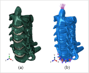
Figure 1: The C2-C7 human cervical spine segment
(a) The eleven parts, vertebrae and intervertebral discs IVDs
(b) An applied compressive vertical load and encastered boundary conditions.
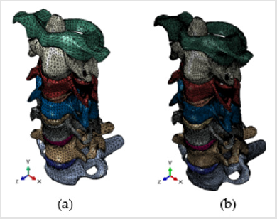
Figure 2: Finite element mesh grids of the C1-C7 human cervical spine segment
(a) Coarse mesh
(b) Fine mesh.
The twelve parts (vertebrae and intervertebral discs) are clearly identified.
The intervertebral disc (IVD) consists of three distinct components: a central nucleus pulposus; a peripheral annulus fibrosus; and two vertebral endplates commonly described as consisting of 2 layers: a cartilaginous layer (also called cartilaginous endplate) that fuses with the disc, and a thin layer of porous bone (also called bony endplate) that attaches to the vertebra. As the vertebral endplates are located between vertebrae and intervertebral discs (gel-filled structures that protect and cushion the vertebrae), they serve as a layer of protection between the hard, bony vertebrae and the softer, more delicate discs. Therefore, contact surfaces and friction coefficients will be considered between the cartilaginous endplates and the discs. The intervertebral disc (IVD) is a cushion of fibrocartilage and the principal joint between two vertebrae in the spinal column. IVDs allow the spine to be flexible without sacrificing a great deal of strength. They also provide a shock-absorbing effect within the spine and prevent the vertebrae from grinding together [6]. In this work, only the vertebral cartilaginous endplate that fuses with the disc will be considered, and the ligaments will be considered as non-linear springs with no effect on compression. The inevitable irregularities in the solid model created by extensible software platforms for image visualization and analysis, such as Mimics [7] or 3D Slicer [8], can be smoothed with a finer FE mesh to reduce stress concentration and improve convergence. Convergence tests will be performed to ensure that the mesh is fine enough for accurate results. Range of motion (ROM) and other results will be validated and compared with published experiment and available finite element results. Nonlinear properties of ligaments, and different properties for each part of the vertebrae and disc will be included in the analysis. Elastic material properties (Young’s modulus E and poison ratio ν) will be assigned to the C1-C7 structure separating the vertebrae and discs in four different material groups:
1) For the vertebrae, the cortical bone properties: E = 12,000
MPa and ν = 0.3;
2) For the endplate, the cartilaginous endplate properties: E
= 3,000 MPa, ν = 0.25;
3) For the peripheral annulus fibrosus: E = 50 MPa and ν =
0.45;
4) For the central nucleus pulposus: E = 1 MPa and ν = 0.49.
Encastered boundary conditions will be used to fix translation and rotation in every node located on the inferior surface of the cartilaginous endplate in the C7 vertebra (Figure 1b).
References
- (2018) ABAQUS. Finite Element Software. Simulia ABAQUS®
- EA Bonifaz (2021) A finite element model of the C1-C4 human spine segment. International Journal of Metallurgy and Metal Physics.
- EA Bonifaz (2021) An elastic finite element analysis of the C2-C7 human cervical spine segment. Submitted to the Journal of Computational and Mathematical Methods in Medicine.
- N Toosizadeh, M Haghpanahi (2011) Generating a finite element model of the cervical spine: Estimating muscle forces and internal loads. Scientia Iranica Transactions B: Mechanical Engineering 18(6): 1237-1245.
- Jeffrey B Barker, Duane S Cronin, Roger W Nightingale (2017) Lower Cervical Spine Motion Segment Computational Model Validation: Kinematic and Kinetic Response for Quasi Static and Dynamic Loading. Journal of Biomechanical Engineering 139(6).
- https://www.physio-pedia.com/Intervertebral_disc.
- https://www.materialise.com/en/medical/mimics-start-page.
- https://buildmedia.readthedocs.org/media/pdf/slicer/latest/slicer.pdf.
