 Mini Review
Abstract
In this paper, based on ANSYS workbench software, a static simulation of the hook and claw component under load conditions is carried out, and its strength is analyzed. The analysis and calculation results show that the weak area of the hook component under the load condition is the hook tooth and the hook shaft. The strength and reliability of this area should be paid attention to in the long-term operation of the equipment.
Keywords: Hook Component; Static Simulation; Strength Analysis
Introduction
The hook and claw assembly is the core moving part of the
control rod drive mechanism. The various actions of the control rod
drive mechanism are realized by the mutual cooperation between
the claws [1]. At present, the hook components often have problems
such as fragile parts and deformation. As the trend of nuclear power
plants participating in the peak shaving operation of the power grid
becomes more and more obvious, the industry has gradually put
forward the demand for ultra-long life of the hook components [2].
The research on hooks in recent years is as follows, [3] studied the
claw surfacing welding process of the driving mechanism in the
third-generation nuclear power and analyzed the claw cobalt-based
surfacing welding process from the aspects of material weldability,
welding method, etc., and obtained the influence of various factors
on the surfacing process [4]. Optimized the surfacing process of the
claws of the reactor drive mechanism based on the finite element
simulation of the claw surfacing process [5]. Aimed at the problem
of the over-tolerance of the inner hole diameter of the hook and
claw shell assembly, analyzed the reason and proposed a solution
under the condition of meeting the design requirements.
At present, the research on the hook and claw components is
mostly focused on the process improvement and optimization of
the hook and the claw is not concerned about the strength of the
hook. This paper analyzes the load condition of the hook and claw
component to obtain the concentrated area or the maximum stress
in the hook and claw component. Strain occurrence area clarify
the weak area of the claw component and provide a reference for
the optimized direction of the claw. The remaining of this study is
arranged as follows. Section 1 introduces the hook components.
Section 2 presents the static simulation analysis of hook and claw
assembly. Section 4 concludes this study.
Introduction to Hook Components
The hook component mainly includes buffer shaft, movable armature, connecting rod, movable hook, hook shaft, connecting rod shaft 1, connecting rod shaft 2, and the cross-sectional view of the hook component structure is shown in Figure 1. The main function of the claw assembly is to engage and loosen the tooth groove of the control rod by extending and retracting, thereby driving the control rod assembly to be lifted or inserted.
Static Simulation Analysis of Hook and Claw Assembly
Model Import and Material Properties Setting: According to the actual working conditions, the drive rod and the hook assembly are assembled to make the hook teeth mesh with the drive rod tooth groove. In order to reduce the amount of calculation, the structure simulation model is symmetrically processed, and only 1/3 of the hook assembly model is built. Mold and simplify the model parts (cutting, chamfering, etc.). Refer to the materials of the parts of the hook assembly and assign the material properties of the parts.
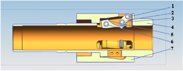
Figure 1: Sectional view of the structure of the hook assembly.
Among them, 1: connecting rod shaft.
2: connecting rod.
3: connecting rod shaft.
4: buffer shaft.
5: hook.
6: hook shaft
7: movable armature.
Meshing: Carry out volume density meshing on the entire model and set the element size to 4mm. In order to improve the calculation accuracy, mesh encryption is performed on the important contact parts. The grid unit size of the connecting rod shaft and the hook axis is 1mm, the grid unit size of the hook and connecting rod is 2mm, and the grid unit size of the hook tooth surface and the driving rod is 1mm.
Add Contact: The connection mode of the kinematic pair between the parts of the hook assembly is consistent with the actual connection mode, that is, except for the movable pair between the movable armature 7 and the buffer sleeve 4. The contact surface between the sleeve and the pin shaft, the tooth of the hook and the tooth groove of the driving rod is the key bonding surface of the model. Set the sleeve and the connecting rod, the sleeve and the moving hook to be in binding contact. The armature and the connecting rod shaft 1, the hook and the connecting rod shaft 2, the buffer shaft and the hook shaft are in binding contact. The contact surface between the sleeve and the pin is set to frictional contact and set the corresponding friction coefficient. The contact surface of the hook teeth and the tooth groove of the driving rod is set to be no-separation, and the analysis setting is set to consider the contact surface.
Boundary Conditions: According to the actual working conditions, add boundary conditions to the hook component. The constraint boundary is added as follows: fixed constraint on the buffer axis, that is, full degree of freedom constraint; the movable armature moves up and down along the buffer axis, and cylindrical support is added to its outer surface to release only the axial degree of freedom; the movable armature is subjected to upward electromagnetic force, which is applied to the armature Add support in the X direction on the surface; the drive rod only moves in the X direction, and the Y and Z constraints are added to it; add frictionless support to the section of the movable armature and buffer shaft. The load boundary is added as follows: add a positive x load at the bottom of the drive rod, and the load value is 540N (the weight of the control rod assembly).
Solve Calculation: Through simulation: Under load conditions, the hook teeth are the area with the greatest stress, and the maximum stress is 382.36Mpa. Among the three pin shafts, the hook shaft is the most stressed, and the maximum stress is 35.106Mpa. Both are smaller than the strength design value, so the strength is reliable. However, in the long-term operation of the equipment, it is necessary to focus on the maintenance and optimization design of the hook teeth and the hook shaft.
Conclusion
This paper takes the hook component as the research object, carries on the static simulation of the hook component under the load condition, obtains the distribution characteristics of the maximum stress and strain of the hook component under the load condition, and conducts the reliability analysis. calculations prove that:
a) Under the load-bearing condition of the claw assembly,
the maximum stress and strain appears at the position of the
claw teeth, followed by the claw axis.
b) At present, the strength of the claws under static
conditions meets the design requirements and the structure is
stable. However, in the long-term operation of the equipment,
the claw components cyclically move back and forth, which
may cause the claw components or parts to fail. Therefore, it is
necessary to focus on the claws Maintenance and optimization
design of tooth and claw shaft.
References
- Wan Yi, Yu Tianda, Yu Zhiwei, Chen Nanxi, Luo Ying, et al. (2017) Design and Research on Control Rod Drive Mechanism of "Hualong One". China Nuclear Power 10(04): 583- 592.
- Yu Jie (2017) The status quo and development of the control rod drive mechanism of PWR nuclear power plant. Science and Technology Innovation Herald 14(22): 83-85.
- Yang Yatao, Xue Song, Guo Baochao, Qi Danhong, Mi Dawei, et al. (2019) Research on the cobalt-based surfacing process of the third-generation nuclear power control rod drive mechanism. Electric Welding Machine 49(09): 55-59.
- Chen Nannan, Yang Fangliang, Yang Xiaochen, Yu Tianda, Deng Qiang, et al. (2016) Research on the design and manufacture optimization of the hook and claw of the driving mechanism of "Hualong No. 1" reactor. Mechanical Design and Manufacturing Engineering 45 (10): 74-78.
- Chen Miaoxin (2015) Cause analysis and honing treatment of the inner hole diameter of the claw shell assembly of the control rod drive mechanism of the nuclear power plant. Mechanical Engineer (12): 224-226.
