 Research Article
Abstract
The purposes of this paper were to determine and evaluate the impact of an implant inclination on strain of the polyurethane resin block using two methodologies, the Finite Element Analysis (FEA) and the Digital Image Correlation technique (DIC). Additionally, to validate the DIC models for strain analysis of the inclined implant using Finite Element Analysis. Four three-dimensional FE and the same number of the DIC models of implant and a polyurethane resin (F16, Axson Technologies, France) block were developed to analyze the influence of an implant inclination on strain on the outer and inner surface of resin block. The Strauman cylindrical dental implant systems (4 x 12 mm; Straumann, Basel, Switzerland) were placed in the polyurethane resin (F16, Axson Technologies, France) block with an inclination of the vertical axis in interval of +1, -1 and -3 degrees. Highest von Mises strains of 0.7 % are in the block implant interface for the inclination of -3˚. Quantitatively similar values were found in the surface of interests between numerical and experimental model. Experimental models analyzed using DIC showed higher strain on the surface of interest than numerical models. Nevertheless, there was no statistical significance in the overall strain field between these regions and modes (p > 0.05, one–way ANOVA). Increase of the angle of inclination increased overall strain in the apical region of the DIC and FEA models. DIC mode confirmed findings supported by FEA modes regarding surface of interest.
Summary
Objective: The purposes of this paper were to determine and evaluate the impact of an implant inclination on the strain of the polyurethane resin block using two methodologies, the Finite Element Analysis (FEA) and the Digital Image Correlation technique (DIC). Additionally, to validate the DIC models for strain analysis of the inclined implant using Finite Element Analysis.
Methods: Four three-dimensional FE and the same number of the DIC models of the implants and a polyurethane resin (F16, Axson Technologies, France) blocks were developed to analyze the influence of an implant inclination on strain on the outer and inner surface of resin block. The Strauman cylindrical dental implant systems (4 x 12 mm; Straumann, Basel, Switzerland) were placed in the polyurethane resin (F16, Axson Technologies, France) block with an inclination of the vertical axis in interval of +1, -1 and -3 degrees.
Results: Highest von Mises strains of 0.7 % are in the block implant interface for the inclination of -3˚. Quantitatively similar values were found in the surface of interests between numerical and experimental models. Experimental models analyzed using DIC showed higher strain on the surface of interest than numerical models. Nevertheless, there was no statistical significance in the overall strain field between these regions and modes (p > 0.05, one–way ANOVA).
Conclusion: Increase of the angle of inclination increased overall strain in the apical region of the DIC and FEA models. DIC mode confirmed findings supported by FEA modes regarding surface of interest.
Keywords: Finite Element Analysis; Digital Image Correlation Technique; Implant
Abbreviations: FEA: Finite Element Analysis; DIC: Digital Image Correlation Technique; AR: Apical Region; VMs: Von Mises strains
Introduction
Undesirable bendings of dental implants should be eliminated
whenever situation allows this. Dental implants should be set in
vertical position, parallel with axial occlusal loads and orthogonal
to the occlusal plane [1-4]. This is sometimes hard to achieve due
to certain limitations in anatomy or histology of supportive tissues
[4-7]. Thus, there are situations where an inclination of dental
implants is inevitable and requested. Additionally, the implant
inclination sometimes accidentally occurs, due to surgeon’s
inexperience or occlusal overloading [4,5,8]. In dentistry, this
accident is usually treated as an iatrogenic error. Therefore, it is very
important to understand the biomechanics of the inclined implants.
An inclination of implant body is important issue in biomechanics
and can compromise the treatment outcomes [3]. The implant
inclination demonstrated effect on the surrounding bone structure
which has been proved previously [1,3,4,9-15]. Experimental
analyzing of stress and strain in jawbone and implant-adjacent
structures has already been conducted [4,16,17].
3D Finite Element Method (FEA) and Digital Image Correlation
Method (DIC) were highlighted as reliable tools for analysis of
different models [13]. Recent reports presented DIC as mighty tool
for measuring strain on the PMMA-acrylic block, subjected to axial
loading of immersed dental implants [18-20]. This study was based
on previously published experimental and numerical investigations
[7,20,21], however, this paper was conducted employing both, FEA
and DIC methods to create critical overview of strain analysis in
resin models with different implant angulations. The goal of this
work was to find connection between implant inclination and strain
of the polyurethane resin block; furthermore, to determine the
regions of the highest strain on the models using two methodologies,
the Finite Element Analysis (FEA) and the Digital Image Correlation
technique (DIC). In addition, to validate and prove the DIC models
for strain analysis of the inclined implant using FEA.
Materials and Methods
Equalization of the Numerical and Experimental Conditions
Four three-dimensional software (FE) and the same number of the experimental models (DIC) of the implants and a polyurethane resin (F16, Axson Technologies, France) blocks were produced to analyze an impact of the implant inclination on strain on the external (outer) and internal (inner) measuring surface of resin block. Dimensions of the blocks-models were 14.5 x 13 x 11.5 mm. The Strauman dental implants (cylindrical, 4 x 12 mm; Straumann, Basel, Switzerland) were immersed in the polyurethane resin (F16, Axson Technologies, France) block. The inclinations of the vertical axis were +1, -1 and -3 degrees. Following this procedure additional control FEA and DIC models with straight implants (one for each analyzing system) were created to compare results obtained for inclined implant models. Height and length of the block were 14.5 mm and 11.5 mm, respectively (Figure 1). A sample-with corresponded to the surface of interest was measured on 13 mm. The distance between the external layer of cylindrical implants and the region of interest was 2 mm. Two locations i.e. modes were analyzed: “block implant” interface/cross section, and the surface of interest i.e. Area/region of interest.
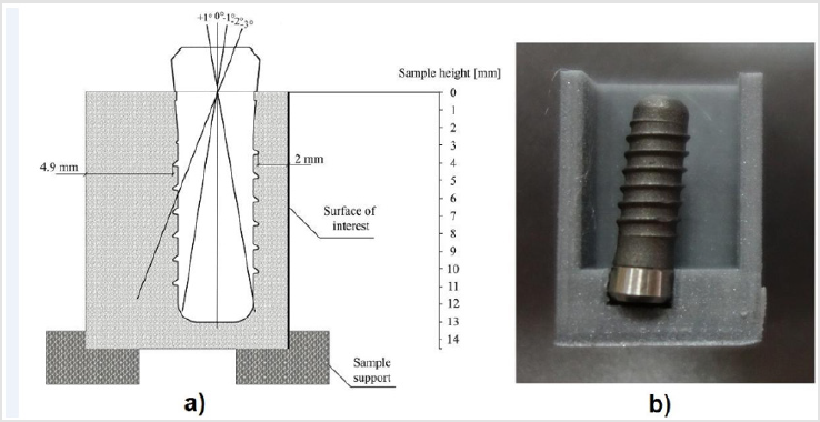
Figure 1: a) Schema of implant inclinations
b) Implant position in resin block.
To facilitate the interpretation of the results, we divided region
of interest into three locations (segments): the cervical (CR), the
middle one (MR) and the apical region (AR). Applied load was axial,
static with the intensity of 500 N [15]. As previously conducted,
model was fixed using both sides of the block while the base
was supported using other two directions [20]. On the surface of
interest (measurement surface), section line 0 was highlighted,
parallel to implant axis (Figure 2a). The area of interest is adjacent
to implant, and thus percepts characteristics of the implant design
[20]. The length i.e. height of the sample was measured from the
top to the bottom, as presented in Figure 1. Horizontal strain was
interpreted as a deformation that occurs in horizontal direction
and reflects movements of implant body and consequently PMMA
due to elasticity phenomenon. An interface presents region closest
to the implant where observed the horizontal strain. Vertical strain
was displayed in the surfaces of interest. In order to compare strain
fields for interface and surface of interest modes (FI, FSI and DIC),
between numerical and experimental model, von Mises strain
values were averaged for cervical, middle and apical region of the
implant. For statistical test was selected one-way ANOVA.
It was used to compare strain on surfaces in models with
different implant inclinations. Analysis was performed in package
“stats”, software R (Vienna, Austria). Null hypothesis was set as
there are no differences in overall strains in the numerical and
experimental model: μFI = μFSI=μDSI and alternative hypothesis as
μFI ≠ μFSI≠μDSI. Level of significance to reject null hypothesis was
set top≤0.05.
Modelling of the FEA Models
Model composed of implant and resin block was obtained using
solid modeling with Ansys 13.0 APDL Multiphysics in Windows 7
OS. Finite Element Analysis was conducted in software program
Ansys 13.0 by Sparse solver. Implant axis was placed parallel to the
width of the area of the interest. Implant thread form was modeled
with 1.25 mm size. One load step with ten sub steps was used.
Results were analyzed in General Postprocessor. Elastic Von Mises
strains (VMs) for all modelled cases are obtained. The contour plots
were served for better comparison of equivalent Von Mises strain in
the region of interest. Strain distribution showed expected layout.
Each color in results corresponds to the certain level of strain in
percent, in accordance with the color scale within figures. The
intersection point of vertical implant axis and upper surface of
polyurethane resin was served for inclination modelling (Figure 1).
Positive inclination of the implant corresponded to situation where
the implant neck was inclined away from the measured surface,
while negative described implant inclination towards it (Figure 1).
Straight model was referred as a model with no inclination (0˚).
Commercial software ANSYS 13.0 was used for FE analysis.
The contact zone between implant surface and polyurethane resin
surface was described as inherent and frictionless. All nodes on the
contact surface between implant and acrylic block were merged.
No Separation option was used. The three-dimensional FE models
shown in Figure 2 consisted of about 260 000 elements and about
348 000 nodes. Mesh density is varied through the model, and it
becomes finer towards the contact surface between implant and
block (Figure 2b).
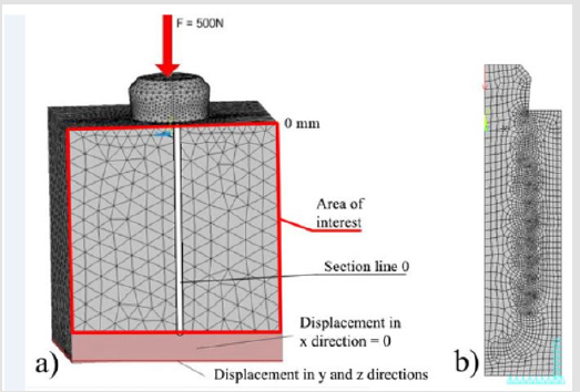
Figure 2: a) Schema of FEA surface of interest
b) FEA interface.
Fabrication of the DIC Models
Experimental models of the block were produced for every angle of inclination and for non-inclined implants. The block mold models were created using Solidworks 2015 Academia (Dassault Systemes). At the bottom of every mold specific opening was created which served as a support of the implant neck under specific angled. This way, the implant could be retained in the position during mixing of polyurethane resin. A cross section of the mold model was presented in Figure 1b. The model was exported into the stereo lithography format (stl) file and imported to Cura software (Ultimaker), where final printing settings were specified. Printing was performed on the Ultimaker 2+ 3D printer (Ultimaker). Immediately after initial preparing and spraying (coating), experimental models were tested on a H10K-S UTM Testing machine (by manufacturer Tinius Olsen, USA) with 5 kN load cell, as described in previous studies. DIC was used to visualize the strain field in the outer surfaces (surfaces of interest) of loaded experimental models. Before a static, experimental compressive loading was conducted, the surfaces of interest were sprayed so they can be visualized later, during the calibration, photographing, optical measuring and Aramis software data processing. Thus, virtual DIC models i.e. DIC images visualized only vertical strain during vertically loading conditions. All, qualitative and quantitative results correspond to the max. load of 500 N. Intensity of strain field was visualized using the color scale in the bottom of each figure.
Results
Control model (Figure 3) showed a uniform distribution all around implant body with higher strain toward the implant apex. Surfaces of interest displayed higher strain concentration around implant apex (Figures 3-9) with consecutively increasing of the strain towards implant inclination, while interfaces showed almost symmetric strain distribution between the surfaces of implant and surfaces of polyurethane resin, with slightly inclining towards the implant apex displacement. VMs was distributed across the surfaces of interest and interface. VMs in all three modes (FI, FSI and DIC) with -1˚ inclination (Figures 5 & 8) showed lower values in the cervical region. The highest values of VMs were in the apical regions, in the bottom of the block, below implant apex. in all three modes whether the numerical or experimental models which is supported by contour plots (FEA modes) or DIC scale (DIC mode). The interface region induced the highest strain with 1 %. Surface of interest strained 0.3 % in numerical model, and 0.35 % in experimental model. Strain for the +1˚ inclination (Figure 4) was similarly distributed like in the case -1 (Figure 5), but the difference can be seen in the apical region with strain of 0.8 %. Surface of interest, for apical region, showed 0.3 % for numerical, and 0.45 % for experimental model. Inclination of - 3˚ was the highest inclination evaluated in this study (Figures 6 & 9). Surface of interest in numerical and experimental model shows 0.37 % and 0.5 %, in the apical regions of dental implant.
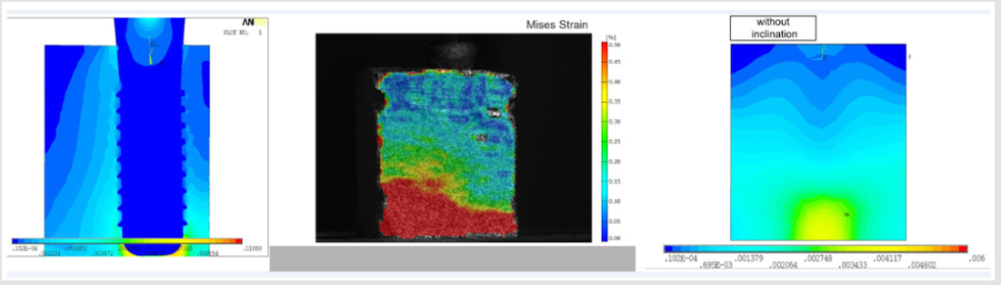
Figure 3: a) Von Misses strain in the FEA and DIC models with uninclined implant.
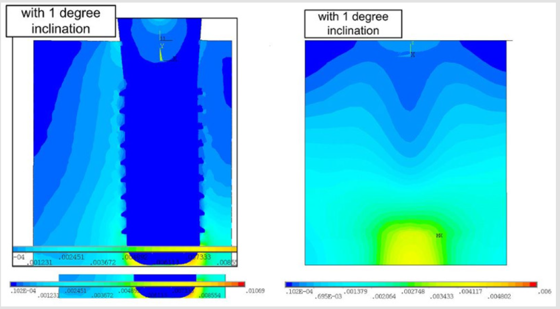
Figure 4: Von Misses strain in the FEA model with 1-degree inclination of implant.
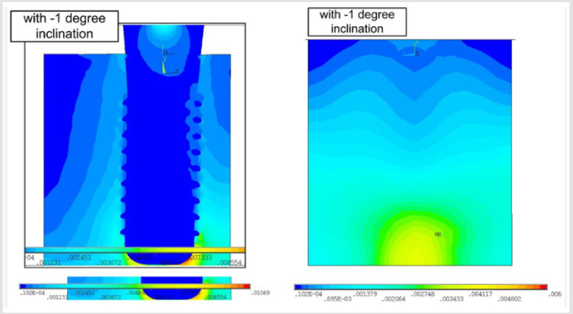
Figure 5: Von Misses strain in the FEA model with -1-degree inclination of implant.
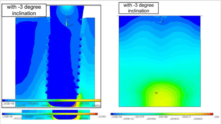
Figure 6: Von Misses strain in the FEA model with -3-degree inclination of implant.
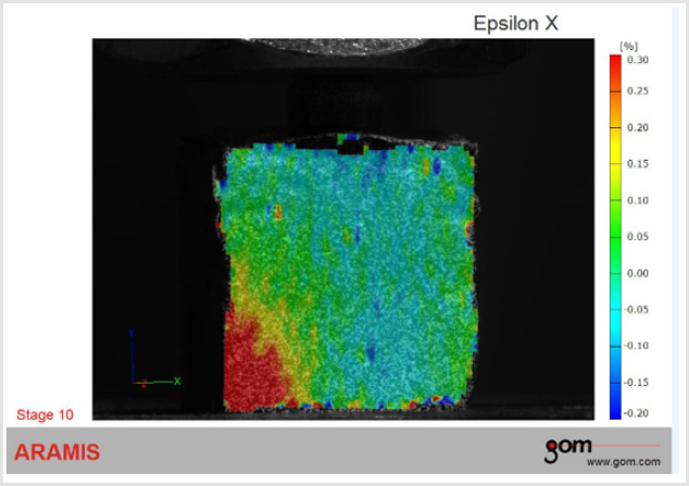
Figure 7: Von Misses strain in the DIC model with 1-degree inclination of implant
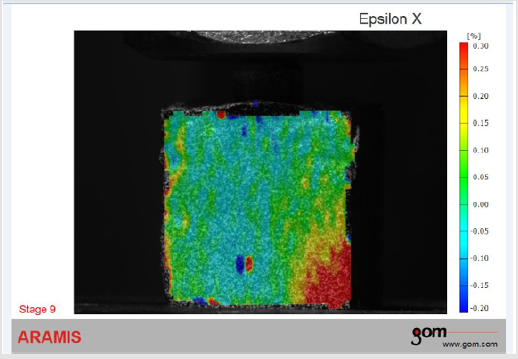
Figure 8: Von Misses strain in the DIC model with -1-degree inclination of implant.
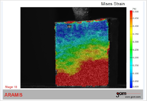
Figure 9: Von Misses strain in the DIC model with -3-degree inclination of implant.
Average strains in cervical, middle and apical regions were calculated as overall von Mises strain for every sample. These values were then compared between interface (FI), surface of interest in the numerical model (FSI) and surface of interest in the experimental model (DSI). Strains were compared to the same inclination angle of dental implant. Highest von Mises strains of 0.7 % are in the block implant interface for the inclination of -3˚. Quantitatively similar values were found in the surface of interests between numerical and experimental model. Experimental models analyzed using DIC showed higher strain on the surface of interest than numerical models. Nevertheless, there was no statistical significance in the overall strain field between these regions and modes (p > 0.05, one–way ANOVA). ANOVA revealed no significant results between three groups for the same levels of dental implant inclinations. In the block-implant interfaces, as expected, were found the highest strains. Regarding the implant inclination, this was almost two or three times higher than strains found in the outer surface of the block. However, one-way ANOVA did not show significant differences between modes (Table 1).
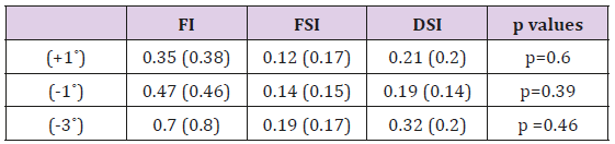
Table 1: von Mises strain for FI (Finite element model - interface), FSI (Finite element models –surface of interest), and DSI (Digital Image Correlation – surface of interest). (Mean ± SD) considering inclinations of +1, 1 and -3.
Discussion
This work shows the significance of using resin models to improve an understanding of the load distribution. The goal of this study was not to determine absolute strain values, however, to compare strain levels following various inclinations of dental implants implant inclinations. FE analysis used the universal material properties with absence of sufficiently accuration for its simulating work. The results of this study might be significant due to obviously relation between deformation and angle of inclination. DIC method was used to determine and analyses surfaces strain induced by loading of non-inclined and inclined implants. Additionally, the study found no significant difference between FEA and DIC results regarding surface of interest. Thus, it can be assumed that DIC technique confirmed results obtained using Finite Element Analysis, regarding surface of interest. The study included 12 modes of the investigated surfaces; four FEA “block implant” interfaces (4 FI, cross section), next four considering the FEA surfaces of interest and another 4 for DIC surfaces of interest (4 FSI and 4 DSI), see Table 1. These modes with straight (control modes, Figure 3) and angled implants (experimental modes, Figures 4-9) were designed to investigate the effect of the dental implant inclination whether on the resin-implant interface or on the region/surface of interest. Full contact between implant and block was presumed. Generally, results for all models have shown the highest von Mises strains in the apical regions, considering the model or the region. Quantitative differences in strains between FSI and DSI region could be attributed to the modeling of an ideal contact between block and dental implant, and materials characteristics which were modeled as isotropic using the FEA performances. Load transfer of inclined implant was frequently researched in splinted dentures or implant supported fixed partial dentures [1,3,4,9,10,11,12,15].
Attempt of this study was to examine the effect of inclination of the implant embedded in the resin block, in the straightforward arrangement, like the already published reports [20]. The use of a polyurethane resin (F16, Axson Technologies, France) to simulate bone seems better than PMMA, as the elastic modulus is more like that observed by human bone. The bottom of the block indicated the highest VMs values located in the interface adjacent to implant apex. An increasing the negative angle values of the implant inclination showed increased values of VMs in the lowest part of the resin block. The design/form of the implant apex and the reaction between base and sample could be the reason of higher strain in the region of implant apex, which is supported by previous findings regarding cancellous models [22].
Our results are consistent with previous studies stated that inclined implant negatively affected on stress/strain field [7,9,12]. FEA contour plots and DIC scales for vertical strain indicate remarkably higher strain in the region of the implant neck corresponds to the top of resin block, which was also reported previously [7,11,23]. Resin material used in this study expresses similar physical characteristics compared to cancellous bone especially considering Young modulus (1.3 GPa vs. 1.37 GPa) [24]. Load intensity was applied in accordance with the values for occlusal forces found in the literature [25,26]. An advantage of this study is found in increased number of the inclination angles compared to other reports [7,9,14]. Nonetheless, it was reported that this change in inclination can be noticed following implantation procedure, due to iatrogenic fators [8], while the effects of this factors should be argued.
Conclusion
As confirmed, block-implant interface exibited higher strain compared to the area of interest considering the inclined implant. Apical region of the DIC and FEA models with inclined implants showed higher strain in the area of interest, while overall strain was found to be higher in the block-implant interface compared to the area of interest. DIC analysis confirmed results obtained by FEA, thus FEA models supported DIC models in term of validation. Results of this study should be utilized for future biomechanical research analysis using DIC or FEA models. This could help to avoid therapeutic failure in implant dentistry.
Acknowledgment
The authors are grateful to Faculty of Mechanical Engineering for technical support and to Neodent (Belgrade, Serbia) for providing the material used in this study
Conflict of Interest
All authors disclose any financial and personal relationships with other people or organizations that could inappropriately influence (bias) their work. The potential conflicts of interest include employment, consultancies, stock ownership, honoraria, paid expert testimony, patent applications/registrations, and grants or other funding.
References
- Behnaz E, Ramin M, Abbasi S, Pouya M, Mahmood F (2015) The effect of implant angulation and splinting on stress distribution in implant body and supporting bone: A finite element analysis. European Journal of Dentistry 9(3): 311.
- Brown SDK, Payne AGT (2011) Immediately restored single implants in the aesthetic zone of the maxilla using a novel design: 1-year report. Clinical Oral Implants Research 22(4): 445-454.
- Gul BE, GSC (2014) Finite Element Stress Analysis of Overdentures Supported by Angled Implants. Merit Research Journal of Medicine and Medical Sciences 2(9): 196-206.
- Markarian RA, Ueda C (2007) Stress Distribution after Installation of Fixed Frameworks with Marginal Gaps over Angled and Parallel Implants: A Photoelastic Analysis. Journal of Prosthodontics 16(2): 117-122.
- Tian K, Chen J, Han L, Yang J, Huang W (2012) Angled abutments result in increased or decreased stress on surrounding bone of single-unit dental implants: a finite element analysis. Medical Engineering & Physics. 34(10): 1526-1531.
- Hobkirk JA, Havthoulas TK (1998) The influence of mandibular deformation, implant numbers, and loading position on detected forces in abutments supporting fixed implant superstructures. Journal of Prosthetic Dentistry 80(2): 169-174.
- Šarac D, I Atanasovska I, Vulović S, Mitrović N, Tanasić I (2017) Numerical Study of the Effect of Dental Implant Inclination. Journal of the Serbian Society for Computational Mechanics 11(2): 63-79.
- Payer M, Kirmeier R, Jakse N, Pertl C, Wegscheider W (2008) Surgical factors influencing mesiodistal implant angulation. Clinical Oral Implants Research 19(3): 265-270.
- Almeida EO, Rocha EP, Júnior ACF, Anchieta RB, Poveda R (2013) Tilted and Short Implants Supporting Fixed Prosthesis in an Atrophic Maxilla: A 3D-FEA Biomechanical Evaluation. Clinical Implant Dentistry and Related Research 17(Suppl 1): e332-342.
- Cağlar A, Aydin C, Ozen J, Yilmaz C, Korkmaz T (2006) Effects of mesiodistal inclination of implants on stress distribution in implant-supported fixed prostheses. The International Journal of Oral & Maxillofacial Implants 21(1): 36-44.
- Hong HR, Pae A, Kim Y, Paek J, Kim HS (2012) Effect of implant position, angulation, and attachment height on peri-implant bone stress associated with mandibular two-implant overdentures: a finite element analysis. The International Journal of Oral & Maxillofacial Implants 27(5): e69-76.
- Lan TH, Pan CY, Lee HE, Huang HL, Wang CH (2010) Bone stress analysis of various angulations of mesiodistal implants with splinted crowns in the posterior mandible: a three-dimensional finite element study. The International Journal of Oral & Maxillofacial Implants 25(4): 763-770.
- Naini RB, Nokar S, Borghei H, Alikhasi M (2011) Tilted or parallel implant placement in the completely edentulous mandible? A three-dimensional finite element analysis. The International Journal of Oral & Maxillofacial Implants 26(4): 776-781.
- Takahashi T, Shimamura I, Sakurai K (2010) Influence of number and inclination angle of implants on stress distribution in mandibular cortical bone with All-on-4 Concept. Journal of Prosthodontic Research 54(4): 179-184.
- Ueda C, Markarian RA, Sendyk CL, Laganá DC (2004) Photoelastic analysis of stress distribution on parallel and angled implants after installation of fixed prostheses. Brazilian Oral Research 18(1): 45-52.
- Tanasic I, Milic Lemic A, Tihacek Sojic L, Stancic I, Mitrovic N (2012) Analysis of the compressive strain below the removable and fixed prosthesis in the posterior mandible using a digital image correlation method. Biomechanics and Modeling in Mechanobiology 11(6): 751-758.
- Tanasić I, Tihacek Sojić L, Lemić AM, Djurić M, Mitrović N (2012) Optical aspect of deformation analysis in the bone-denture complex. Collegium Antropologicum 36(1): 173-178.
- McCormick N, Lord J (2010) Digital Image Correlation. Materials Today 13(12): 52-54.
- Mitrovic N, Milosevic M, Sedmak A, Petrovic A, Prokic Cvetkovic R (2011) Application and Mode of Operation of Non-Contact Stereometric Measuring System of Biomaterials. FME Transactions 55-60.
- Tanasić I, Tihaček Šojić L, Mitrović N, Milić Lemić A, Vukadinović M (2015) An attempt to create a standardized (reference) model for experimental investigations on implant’s sample. Measurement 72: 37-42.
- Tiossi R, Lin L, Conrad HJ, Rodrigues RCS, Heo YC (2012) Digital image correlation analysis on the influence of crown material in implant-supported prostheses on bone strain distribution. Journal of Prosthodontic Research 56(1): 25-31.
- Geng JP, Tan KBC, Liu GRP (2001) Application of finite element analysis in implant dentistry: A review of the literature. J Prosthet Dent 85(6): 585-598.
- Tanasić I, Tihaček Šojić Lј, Milić Lemić A (2014) Finite Element Analysis of Compressive Stress and Strain of Different Implant Forms During Vertical Loading. International journal of computerized dentistry 17(2): 125-133.
- Ding X, Zhu XH, Liao SH, Zhang XH, Chen H (2009) Implant-bone interface stress distribution in immediately loaded implants of different diameters: a three-dimensional finite element analysis. Journal of Prosthodontics 18(5): 393-402.
- Djebbar N, Serier B, Bouiadjra BB, Benbarek S, Drai (2010) Analysis of the effect of load direction on the stress distribution in dental implant. Materials & Design 31(4): 2097-2101.
- Brunski JAH (1984) In vivo forces on endosteal implants: A measurement system and biomechanical considerations 51(1): 82-90.
