 Review Article
Abstract
A neurostimulator was investigated in this paper posthumously. Device was presented to our anatomical gift program. Investigation was multi-fold and contained visual inspection, using an optical microscope, and mechanical and electrical testing of leads and its insulator. It was concluded that the device could have been damaged during implantation, in vivo, during removal, and/or during transportation to author’s laboratories. The damage observed on the lead insulation is similar to that which can occur due to anchoring of the lead and hardening due to oxidation. Insulation stiffness was determined to be 1/10 of new insulator. The results reported here on the insulation may or may not have affected the electrical operation of the neurostimulator.
Abbreviations: DBS: Deep Brain Stimulation, SCS: Spinal Cord Stimulation, ET: Essential Tremor, OCD: Obsessive-Compulsive Disorder
Introduction
A neurostimulator is a medical device used to perform Deep Brain Stimulation (DBS) or Spinal Cord Stimulation (SCS) in order to provide therapeutic relief to patients suffering from certain movement and psychiatric disorders [1,2]. Examples of disorders that can be treated with the use of a neurostimulator include Parkinson’s disease, dystonia, Essential Tremor (ET), and Obsessive-Compulsive Disorder (OCD). DBS can also be used to treat migraines, multiple sclerosis pain, and amputation pain, while SCS is also used to treat back pain (Failed Back Surgery Syndrome) and other neuropathic pain [3,4,5,6]. In order for the device to stay functional, the entire device must stay intact and be able to deliver the appropriately programmed electronic pulses to the correct portion of the brain or spinal cord in which the leads were implanted. The device under investigation in this report is the Medtronic Soletra 7426 neurostimulator [7,8,9,10]. Inserted similarly to a pacemaker, this model of neurostimulator is comprised of a titanium casing (Figures 1 & 2). On top of the casing is a connector block that connects the lead to the casing [11]. The connector block is made of polyurethane. The neurostimulator has a single channel lead that consists of lead wire coils and insulation. The lead wires are platinum- iridium and the insulation is made of polyurethane. Most disorders treated using DBS and SCS (excluding ET) require bilateral stimulation, suggesting there was more than likely a second neurostimulator in the patient [4]. Several different malfunctions are possible for a neurostimulator and have been documented with the Medtronic Soletra 7426, including but not limited to device- related infection, system migration, battery exhaustion, electrode/lead migration, electrode/lead fracture, and skin erosion [7,3,8,5,6,9,10] (Table 1).
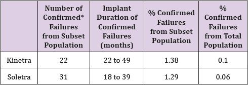
Table 1: Occurrence of Failure of Soletra and Kinetra Neurostimulators as reported by Medtronic.
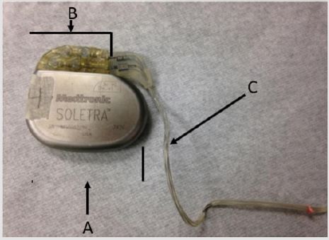
Figure 1: Overview picture of the Medtronic Soletra 7426 neurostimulator; A) Case. B) Connector block. C) Lead.
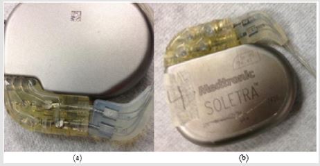
Figure 2: (a) The lead beginning to separate from the connector block, exposing the lead wires to the outside environment. (b) External damage to the casing, discoloration and scratch.
Infections can occur due to the introduction of a foreign material [12]. Failure could also be attributed to electric pulses not being delivered properly to the implanted area. This could occur due to damage to the lead or device caused by the environment of the human body [12]. In this investigation an attempt was made to document the damage on the device posthumously and does not necessarily constitute a failure of the neurostimulator. This analysis will provide insight into the different modes of failure for neurostimulators and could help improve future products. It is worth noting that Medtronic Soletra 7426 has been discontinued and is no longer being manufactured.
Materials and Methods
The specification of Medtronic Soletra 7426 is presented below. The physical, electrical and/or therapeutic properties, lead, and materials of the device are summarized in Tables 2-6. The Medtronic Soletra 7426 could be used for DBS with either the DBS Lead Model 3387 or 3389. This failure analysis will focus mainly on the lead, assuming that pulse generator and program do not fail. A lead has four major components, terminal pin, insulation, conductor coil and tip-electrode [13]. The specifications for both leads were provided by Medtronic. The specific device studied for this analysis is no longer connected to the electrodes, however, data included here for completeness.
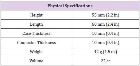
Table 2: Physical Specifications of the Medtronic Soletra 742613.
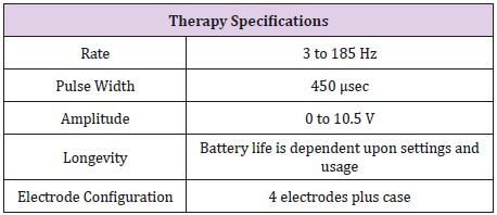
Table 3: Therapy Specifications for the Medtronic Soletra 742613.
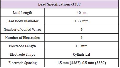
Table 4: Physical Specifications for the DBS Lead Model 3387 and 33898.
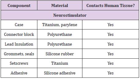
Table 5: Material components of the Medtronic Soletra 7426, including determination of tissue contact during implantation13.
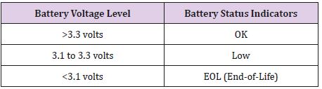
Table 6: Battery Status Indicators for the Medtronic Soletra 7426, battery voltage level measurements are accurate to ±5%13.
The lead of the neurostimulator is considered to be a quadripolar, multifilar, co-radial lead4. The current neurostimulator under investigation has visible signs of damage. These damage features include a scratched casing, separation between the connector block and the lead, missing and damaged portions of the insulation of the lead (Figure 3) and some discoloration on the lead insulation. The bulk of the damage on this device is to the lead insulation, which is not uncommon. Insulation defects are the most frequent cause of lead failure [14]. Figure 2 shows the condition in which the device was received.
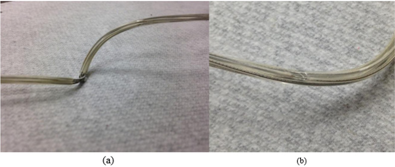
Figure 3: (a) Missing insulation exposing the lead wires, though it is unknown if it happened in vivo or in vitrio. (b) A dent on the insulator.
Lead Continuity Test
Continuity test was conducted on the lead wires of the neurostimulator. A Fluke Multi-meter was used to measure the resistance in the lead wires by clamping the positive lead to the lead wires past the point of damage and by placing the negative lead on each internal port of the all four lead coils. The damage to the leads caused by external exposure was not significant as the resistance meter was able to provide the readings. If the lead coils were discontinuous, the function of the device could have been severely altered. However, the device was retrieved posthumously and may have received additional damages during retrieval.
Axial Stiffness of the Lead Insulation
Tensile tests were performed (Figure 4), on an undamaged portion of the lead insulation to determine the axial stiffness of the insulation. The test was performed using a Test Resources 100, single column electromechanical universal test machine1. This machine can be programmed to perform several different tests. For this analysis, the machine was programmed to place the section of the lead insulation under tension. A fully insulated section of the lead was placed perpendicularly between the clamps of the device. The machine was programmed to move at a rate of 1 millimeter per minute and to stop the axial force after a certain displacement was reached. Figure 4 shows the set-up used for the stiffness testing.
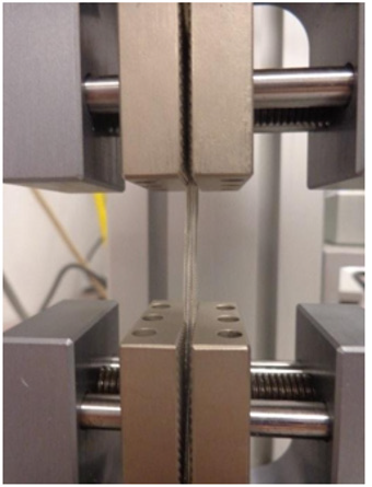
Figure 4: Set up of the tension stiffness test performed on the lead insulation.
Results
Optical Microscope Observations
The optical microscope used for this analysis is the WILD Photomakroskop M400. The insulation was cracked at several places exposing the lead wires. Growth of biological materials was also seen between the insulator and the lead-wires, Figure 5. If the exposed lead wires maintain their protective coating, then the leads are to be considered corrosion free and undamaged observed during this investigation. It is also likely the excessive forces applied to retrieve the device may have damaged the lead, widen its pitch, and likely to pull from connector block assembly. These features are not reported here. These features in Figure 5 are consistent with pulling during retrieval. Also, the lead coils were not broken.
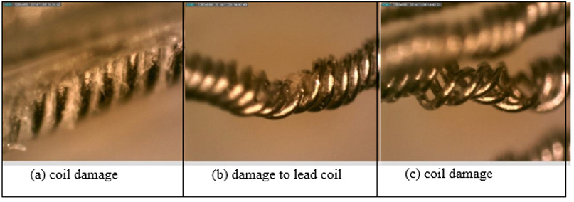
Figure 5: Damage to the lead coil at the site of cracked insulation and other areas.
Axial Stiffness
The tensile test was performed for displacements of 0.25 mm to 0.75 mm with increments of 0.05 mm. Each displacement was performed twice and the load required recorded. Table 8 shows the loads for each displacement for both trials. The axial stiffness was then calculated and presented in the table. The load versus displacement was then plotted for both trials one and two for the max displacement. Applied load versus displacement for the lead insulation plotted in Figure 6a & 6b for two trails, the plot is linear and then eventually starts to plateau around 0.45 mm. This observation is also shown in Table 7, where the axial stiffness values stay relatively similar until a displacement of 0.50 mm is reached. The axial stiffness results from 0.25 to 0.45 mm were then used to find the axial stiffness of the lead insulation. Two plots are combined in a composite in Figure 6 and load to yield or plastically deform the insulator determined to be nearly 4N force which is insignificant Figure 7. From the linear regression equations, one can conclude that the axial stiffness of the lead insulation is approximately 8.9 N/mm. The equations can be used to estimate how much force is needed to displace the insulation a certain length in millimeters as long as the displacement falls in the linear range shown above.
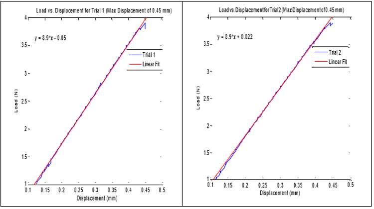
Figure 6: Axial stiffness of lead insulator, linear fit applied to the data within the linear region.
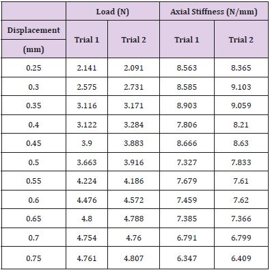
Table 7: Axial Stiffness Results from Tension Trials.

Table 8: Resistance readings for each lead coil from the connector block past the bent portions of the lead coils.
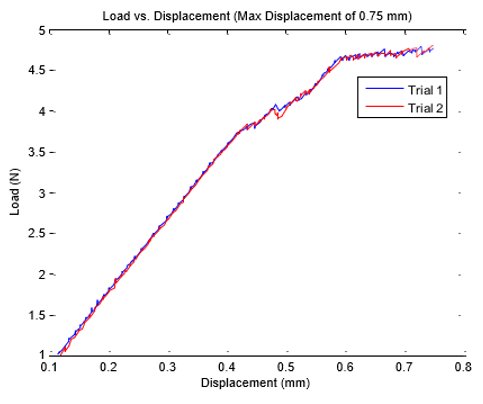
Figure 7: Composite plot of load vs. displacement of the lead insulation showing plateau.
Lead Continuity Testing
The results obtained from the testing are summarized in Table 8. As can be seen in Table 8, all four leads were found to have a resistance from the back of the connector block all the way past the portion of exposure and damage on the lead. This proves that the continuity was intact for all four lead coils between the points measured.
Discussion
The neurostimulator used in this study has an unknown
history. Since the device was retrieved posthumously, the cause of
death, the time that the device was in vivo, when it was implanted,
and patient demography not available for this investigation.
Additionally, the method used to remove the device was also not
available. Therefore, this study not only looks into potential failure
cause of the device, but also the potential of damages to the device
during removal process [15-17].
It was determined that two areas of the lead wires were exposed
due to damage on the insulation. If the lead wires were exposed
while the device was in vivo, it may have affected the local tissue
structure, which was not available for study. Neurostimulators
fail due to the oxidation of lead wires after insulation damage2.
Therefore, observations made from this paper are valuable. The lead wires were not exposed at the separation of the connector
block and the lead, however, the exposed lead wires showed no sign
of breakage. Destructive tests and program interrogation tests were
not possible on this device [18,19].
Typical axial stiffness values of new polyurethane for cardiac
leads are greater than 120 N/mm9. The results of our tensile
tests concluded that the axial stiffness of our polyurethane lead
insulation was about 8.9 N/mm. If the polyurethane material of
the neurostimulator lead insulation is assumed to be similar to
that of a polyurethane cardiac lead, then the axial stiffness of this
device has reduced considerably, an order of magnitude. This could
be due to the aging of the insulation and exposure to the chemical
and biological reactions of the body. Because of the decreased
axial stiffness, may have been due to oxidation, the lead insulation
could crack, of its own, with very little forces that could arise due
to sudden movement, sleep posture or attending to the activities
of daily living. However, because of this reduced axial stiffness, it
is also possible that the insulation could have become damaged,
cracked or run-off during removal [20].
Insulation break up as shown in Figure 3b, was noted in a
predicate study3 neurostimulator, where the patient complained
of returned migraines and a burning sensation in her left
posterior neck triangle. The burning sensation in the patient was
attributed to the exposure of the conducting surface of the lead
wires. After investigation and surgery, it was discovered that the
lead insulation was eroded at the anchor site3. Features reported
in Clarke, are very similar to what we observed in Figure 3b. The
force of the sutures used to anchor the lead along with the flexion
and extension movements of the body at this site caused the lead
insulation to break down. This analogy may be applied to the
present investigation.
Firm anchoring is required to prevent lead migration, which is
the movement of the lead from the original placement. Migration is
a common complication in patients with neurostimul ators [21,22].
Rosenow21 collected data from the Cleveland Clinic of all patients
with neurostimulator hardware failures. Of the 289 patients, 11.4%
experienced problems with lead migration [22]. Because of the
prevalence of this issue, it is possible that the sutures used to secure
the device in this investigation were tied with enough force to
prevent migration, causing the erosion to the lead insulation. The
device could have then ceased treatment or began burning tissue
around the anchor site. The occurrence of this complication could
be proven if a rash was found on the patient’s skin around the neck
area [22,23]. The damage could have also occurred during removal
of the device postmortem due to the decreased axial stiffness of the
insulation.
Because the lead wires are exposed in two different spots along
the lead and it is unknown whether or not this exposure occurred
in vivo or in vitro, it is possible that the lead wires became damaged.
If the lead wires were damaged enough, then the continuity
could have been compromised and the therapy could have been
interrupted. In the test of continuity, if the multi-meter measures a
resistance from one point to another, the lead wire is proven to be
intact. As can be seen in the results in Table 8, all four lead coils are
proven to be continuous from the back of the connector block to
past the damaged portion of the lead wires. Therefore, there is no
evidence to support that any of the lead wires were compromised
despite the exposure and bending seen in the original observations.
If destructive testing were possible for this device, it is possible that
the impedance of the lead could have been measured to compare
with literature values for functional neurostimulators.
Conclusion
It is unknown whether the damage to the neurostimulator occurred when the device was implanted, during in vivo use, removal posthumously, or transportation to the author’s laboratories. The damage to the insulation may have occurred during removal of the device postmortem. Damage to the insulation is consistent with oxidation damage, in vivo, it is similar in appearance to damage caused by anchoring of the lead. The axial stiffness of the lead insulator had reduced more than 10 folds, indicating that the lead could crack due to resisting forces that arise from activities of daily living. There is no evidence that the electrical functionality of the neurostimulator was compromised. This investigation assumes that the device was functional in terms of its program and pulse generator which includes the power source, output circuit, sensing circuit, and timing circuit.
References
- (2014) 100 Family Single Column Electromechanical Universal Test Machine. 100 Family Single Column Electromechanical Universal Test Machine. Web.
- Clarke C, Azari P, Huh B (2011) Damaged insulation mimicked symptoms of occipital stimulator lead migration. Neuromodulation 14(6): 539-540.
- Cruccu G, Aziz T, Garcia Larrea L, Hansson P, Jensen T, et al. (2007) EFNS guidelines on neurostimulation therapy for neuropathic pain. European Journal of Neurology 14(9): 952-970.
- Fiume D, Sherkat S, Callovini G, Parziale G, Gazzeri G (1995) Treatment of the failed back surgery syndrome due to lumbo-sacral epidural fibrosis. Advances in stereotactic and functional neurosurgery 11: 116-118.
- Kalia V, Bizzell C, Obray R, Obray J, Lamer T, et al. (2010) Spinal cord stimulation: The types of neurostimulation devices currently being used, and what radiologists need to know when evaluating their appearance on imaging. Current Problems in Diagnostic Radiology 39(5): 227-233.
- Kumar K, Taylor RS, Jacques L, Eldabe S, Meglio M, et al. (2007) Spinal cord stimulation versus conventional medical management for neuropathic pain: A multicentre randomised controlled trial in patients with failed back surgery syndrome. Pain 132(1): 179-188.
- Coffey RJ (2009) Deep brain stimulation devices: A brief technical history and review. Artificial Organs 33(3): 208-220.
- (2010) Medtronic Soletra: Lead Kit for Deep Brain Stimulation. Implant Manual. Metronic, Inc.
- McGrath, J Pain therapies. Medtronic, Inc.
- Peterson JT, Deer TR (2013) A history of neurostimulation. Comprehensive treatment of chronic pain by medical, interventional, and integrative approaches pp. 583-586.
- Eljamel S (2013) Appendix II: Troubleshooting malfunctioning neurostimulators. Neurostimulation: Principles and Practice 222-230.
- Woods DM, Hayek SM, Bedder M (2007) Complications of neurostimulation. Techniques in Regional Anesthesia and Pain Management 11(3): 178- 182.
- Jenney C, Ta, J, Karicherla A, Burke J, Helland J (2005) A new insulation material for cardiac leads with potential for improved performance. Heart Rhythm 2(5): S318-S319.
- Borleffs CJ, Van Erven L, Van Bommel RJ, Van der Velde ET, Van der Wall EE, et al. (2009) Risk of failure of transvenous implantable cardioverter-defibrillator leads. Circulation: Arrhythmia and Electrophysiology 2(4): 411- 416.
- (2010) Medtronic Soletra: Neurostimulator for deep brain stimulation. Implant Manual. Metronic, Inc.
- Mercado L, Carney JK, Ebert MJ, Hareland SA. Bashir R (2009) Digital health and bio-medical packaging. Materials for advanced packaging pp. 681-712.
- Mullett K, Starkebaum W (1994) Spinal cord stimulator: Design and function. Spinal cord stimulation pp. 65-73.
- Nazzaro JM, Lyons KE, Pahwa R, Ridings LW (2011) The importance of testing deep brain stimulation lead impedances before final lead implantation. Surgical Neurology International 2: 131.
- Ondo WG, Meilak C, Vuong KD (2007) Predictors of Battery Life for the Activa Soletra 7426 Neurostimulator. Parkinsonism Related Disorders 13(4): 240-242.
- (2004) Patente US7831311 - Reduced Axial Stiffness Implantable Medical Lead. Google Books.
- Raphael JH, Mutagi H, Hanu Cernat D, Gandimani P, Kapur S (2009) A cadaveric and in vitro controlled comparative investigation of percutaneous spinal cord lead anchoring. Neuromodulation 12(1): 49-53.
- Rosenow JM, Stanton-Hicks M, Rezai AR, Henderson JM (2006) Failure modes of spinal cord stimulation hardware. Journal of Neurosurgery Spine 5(3): 183-190.
- Sarwat AM, Karanth KS, Sutcliffe JC (2000) A rare complication of hardware failure in neurostimulation: Report of two cases. Journal of Neurosurgery Spine 93(2): 330-331.
