Abstract
This study presents novel predictive equations for von Mises stress values of bones in the frontal and lateral regions of the skull. The equations were developed based on results of a finite element model developed during this research. The model was validated for frontal and lateral loading conditions with input values mimetic to fall scenarios. Using neural network processing of the information derived from the model achieved R2 values of 0.9990 for both the stress and deflection. Based on the outcome of the fall victims, a threshold von Mises stress of 40.9 to 46.6 MPa was found to indicate skull fracture given a maximum input force of 26 kN and a load rate of 40 kN/ms.
Introduction
Several modes of injury exist in the general term of “traumatic
brain injury” (TBI), which is termed a “silent epidemic” and has
an estimated annual cost of 76.5 billion dollars by the Centers
for Disease Control [1-17]. While the term is usually used to refer
specifically to brain damage, skull fracture is almost always lumped
into the category. Skull fractures do not always directly pose a risk
for brain injury, although the conditions that cause them to form
do. These conditions also lead to the formation of life-threatening
conditions including hematoma or damage to the nerves of the
brain due to the extreme conditions imposed upon the soft tissue.
Additionally, some modes of skull fracture, such as depressed
fractures, can put direct pressure on the brain, causing significant
brain damage. While TBI can occur at thresholds lower than those
needed to cause skull fracture, fractures are often lumped into the
general category of “traumatic brain injury” and depending on the
nature of the fracture, can indicate for the presence of, or indeed,
the severity of any brain damage [1-8]. Skull fracture’s likelihood
varies based on the location struck, due to the varying thicknesses
and orientations of the bone.
The exact variety of fracture depends on the intensity, location,
and other factors relating to the blow. In higher energy collisions,
direct bending of the bony structure of the skull can result in
fracture by strains directly from the impact, forming a depressed
fracture. Linear factures can develop outside of the primary
strike area. However, due to the elastic nature of bone tissue and
outbending that develops secondary to the strike the injury may
occur [7]. Linear skull fractures by themselves do not tend to
provide complicating factors to an injury, but depressed fractures
can physically press upon the brain, causing further damage [8].
Falls are the most common cause of TBI, accounting for about a
third of all cases [4]. Fall-induced TBI death rate for persons 80
years and older increased to 38.1 per 100,000 persons despite an
increase in the self-reported average health of the age group [14].
Typically, falls consist of blunt impacts due to the head striking the
ground, although depressed or penetrating injuries can occur from
hitting a corner such as the edge of a sidewalk or a table.
Though they are often at lower energy compared to a motor
vehicle collision, falls can readily cause skull fracture due to the
potential energy release of a fall [6]. This is often accentuated
as many falls happen in stairwells, where multiple impacts are
possible. Fall injuries most often appear in either single or multiple
impacts around the “hat brim area,” a 3 cm thickness region around
the head with a lower limit formed from the circle connecting the
top of the eyebrows to the occipital pole [10]. Assault, especially
in abuse cases, can also present with similar symptoms, although
some research has shown the assault injuries tend to occur on
the left side of the skull. Finite element models of the skull have been used in the past, however these are generally directed at soft
tissue injury and model the skull itself at low resolutions. Other
established head models contain a relatively small number of
elements, such as a model developed in 1980 has 637 elements.9
More modern models include 19,417 elements and 17,651 nodes
and the ULP model, which contains 10,500 elements and 12,000
nodes [15-17]. Not all these elements are included in analysis for
the skull however; in both of these, elements are allocated for
tissues other than the skull.
Materials and Methods
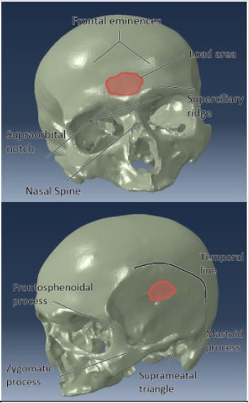
A converged finite element model was constructed to model the events of fall injuries. The model used was developed using a CT scan of cadaveric head of an adult male. The CT scan used a slice thickness of 0.95 mm in each orthogonal direction. Maximum dimensions of the skull were 156.3 mm in the transverse plane, 186.3 mm from brow to the external occipital protuberance, and 143.0 mm from the vertex to the foramen magnum. Average skull thicknesses at the frontal bone were 7.82 mm, 7.80 mm for the occipital bone, 6.21 at the vertex, and 6.42 mm for the temporoparietal bone. Thresholding of bone was carried out from the model using Mimics software. The solid body model created used a maximum element length of 4 mm to form the mesh. The model contained 209,188 nodes and 969,575 tetrahedral element topology 4 elements (TET4). These elements are the simplest arrangement of nodes and will sacrifice some accuracy in favor of speed when used at low mesh densities. It was then exported into ABAQUS for finite element analysis where it was converted into Continuum 3-D, 4 node element types (C3D4), which are also tetrahedral in shape. These elements have three integration points for each direction, for a total of 27 integration points per element. The high density used in this model improved upon the accuracy and made them enough for calculations. The skull was modeled as a viscoelastic body as it is well known in literature that wet bone, as experienced in vivo, contains a viscoelastic element. Inclusion of these terms into the model here sought to improve the overall accuracy of the model. An elastic modulus of 18 GPa, density of 2000 kg/m3, and a Poisson’s ratio of 0.3 were used per common literature values. Prony series terms for viscoelasticity of 0.1346 Pa for Gi and 117.85 s for τi were used [5]. Prony series analysis utilizes a minimization algorithm that corrects for errors between the predicted and measured values to represent the viscoelastic nature of the data. It then decomposes the data in a matter like that of a Fourier transform. Forces were uniformly distributed over a 300 mm2 area in the “hat brim” region for the frontal and lateral locations to mimic the area impacted in falls as this is the most common region of the skull to be impacted in a fall. The area that the impact covers in a typical fall depends upon the object struck.
A sharper, more pronounced, or stiffer object would tend to present with a smaller impact area. The frequency with which different objects are struck was not available in literature at the time, so typical areas of impact in a fall are not agreed upon. The value of 300 mm2 was chosen as a value that would be comparable to the size of the hat brim area. The lateral force distribution was centered 53.9 mm over the suprameatal triangle and 57.5 mm dorsal to the frontosphenoidal process. It consisted of a roughly elliptical shape following the contours of the element borders of the skull with a semi-major radius of 12.1 mm and a semi-minor radius of 7.65 mm. The frontal force profile was centered over and located 40.7 mm above the nasal spine and was likewise an ellipsoid following the contours of the elements on the skull. The semi-major radius was 12.28 mm and the semi-minor radius was 7.98 mm. These locations and approximate force areas can be seen in Figure 1. The magnitude used for the force was also designed to mimic the forces experienced in a fall. Fall data was reconstructed and several force versus time plots were created based on the differing situations. Maximum forces for each simulation were found to range from 10 to 50 kN and maximum load rates between 10 to 100 kN/ms [11]. Forces in the simulation were assumed to be directed normal to the skull, pointing towards the interior. These plots were digitized in order to generate an equation for force as a function of time. The medium force value (case 2) was used here and fit to the 9th degree polynomial seen in equation 1 from t=0 ms to t=2.5 ms with an R2 of 0.998. This equation was then adjusted to account for changing load rates and maximum forces.
Force =1236t9 −145961t8 + 73420t7 − 2049679t6 + 3448499t5 −3517100t4 + 2036925t3 − 572817t2 + 8181788t − 4424...(1)
Figure 1: Force location with respect to anatomical landmarks on the skull for (top) front and (bottom) lateral modalities.
Results
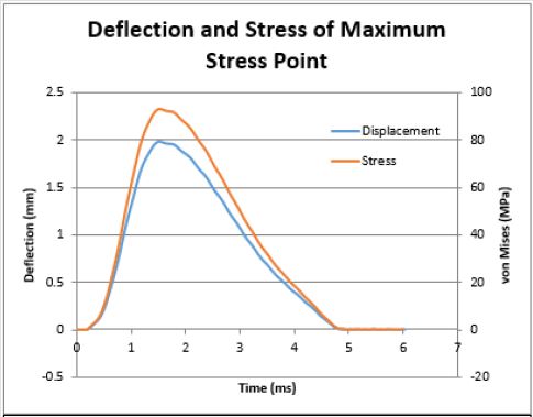
Statistical analysis of results was carried out using JMP statistical software. To avoid isolated outlier points due to artifacts of the discretized finite element process, the 99.993rd percentile data point was used for each analysis. Von Mises values ranged from 13.95 MPa to 94.97 MPa depending on the input parameters of the simulation, with higher load rates and maximum loads developing a larger von Mises stress. Figure 2 shows the loading and deflection of this element in a stress over time diagram of the simulation with a maximum applied force of 50 kN and a maximum load rate of 50 kN/ms. In the frontal and lateral cases, most of the stress distribution was seen at the contact site of the force, with some areas of high magnitude extending from the site. Most noticeably in the lateral tests, some force was seen in the sinuses, with a concentration in the sphenoid. The concentration seen at the sphenoid for lateral tests was 40% of that of the peak force seen at the contact site. Least squares analysis upon the input variables of location, maximum force, and maximum force rate was performed. These values were found to be significant at P<0.0001 for each variable. In addition, the combination terms of (load)*(load rate) (P=0.0001) and (load)*(location) (P<0.0001) were found to be significant to the calculation. Other variables did not show enough evidence for significance.
Figure 2: Stress and deflection of the over time of the maximum stress point for this load for the lateral, 50 kN max load, 50 kN/ms trial.
Discussion
The previous least squares examination yielded the general
equation shown in equation 2, which was a linear combination of
terms for the maximum von Mises stress with inputs of kN and kN/
ms. This equation was developed between a maximum load of 10 to
50 kN and a maximum load rate of 10 to 100 kN and achieved an R2
value of 0.994. Impacts to the frontal region use a value of 0 in the
case functions and lateral impacts use a 1. Because experimentation
was not able to be done on a continuum of points, the location
parameter should be treated as an ordinal variable.
Maximum von Mises Stress
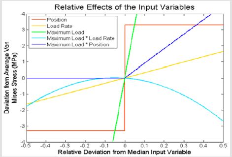
A graphical depiction of the effects that these variables have in relation to each other can be seen in Figure 3. Based on these results, each factor influences the von Mises stress in a different way. As to be expected given the results seen previously, maximum force and loading rate caused the von Mises stress to increase over time, although an increase in the maximum force causes a more pronounced effect over the ranges used here. Additionally, as to be expected given that position is an ordinal variable, the effect of changing location is manifested as a step function. Load crossed with load rate causes the effect decreasing the von Mises stress as values move from the median input value.
Figure 3: Relative scale of the effects of the input variables on von Mises stress based on least squares analysis. All variables were scaled from their minimum and maximum inputs to fit from -0.5 to 0.5. For example, -0.5 corresponds to the minimum load rate of 10 kN/ms, while 0.5 corresponds to a load rate of 100 kN/ms.
The peak von Mises stress seen from this term is at -0.052, which corresponds to a maximum load of 27.9 kN and a maximum load rate of 50.1 kN/ms. The other term, load crossed with position, displays an increase in the von Mises stress for impacts on the lateral side of the skull, but not for the frontal region. The profile created by this curve shows effects of the geometry of the skull as well as the ordinal nature of the location input upon stress formation. In addition to the least square’s equation, a neural network model was also used. The model used the holdback method with a holdback proportion of 0.3333 with 3 hidden nodes. This created an initial model of the data with an R2 value of 0.9997. It was then validated at 0.9990, showing a better fit of the data than shown in the least square’s analysis. This equation was developed between a maximum load of 10 to 50 kN and a maximum load rate of 10 to 100 kN. Impacts to the frontal or lateral regions use the value designated in their choice functions. Again, location should be treated as an ordinal parameter. The neural network equation can be seen in equation 3.

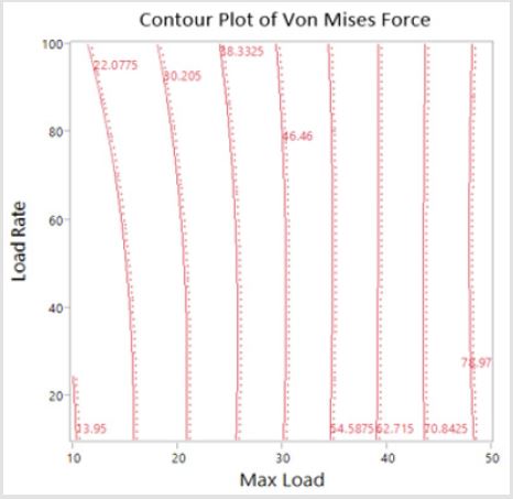
Inputs for maximum load are kN and inputs for maximum load rate are kN/ms. Output is in units of MPa. This model, while daunting at first glance, is easily used in computation. Effect testing for the model gives weights for the importance of variables in contributing to the overall effect. Maximum load had a relative effect of 0.484, position had an effect of 0.013, and load rate had an effect of 0.003. Though diminished compared to the maximum load, the effect of the load rate and its decreasing effect with greater maximum loads is still clearly visible in Figure 4. The lowest predicted value using the boundaries of the input parameters was at maximum load rate = 10 kN/ms, maximum load = 10 kN, and frontal analysis. This yielded a maximum stress value of 13.56 MPa, compared to the lowest recorded value of 13.95 MPa. This was more accurate than the least squares value by a factor of 6.3. A maximum predicted value at load = 50 kN, load rate = 50 kN/ms, lateral mode gave a prediction of 95.20 MPa compared to the observed 94.97 MPa. This also gave a more accurate result to the observed maximum when compared to least squares, by a factor of 15, rendering it a more complicated, but more accurate model of the data.
Figure 4: Contour plot of the Von Mises stress from neural network with respect to maximum load and load rate. Contours are lines of the specified von Mises value.
Conclusion
Comparison of the values shown here can be made to the outcomes of falls published in literature. Fall reconstruction in this paper revealed that force loading of at least 26 kN and 40 kN/ms were found to cause skull fracture. While the sample size for this study is limited, the corresponding von Mises value for these parameters using the neural network model is 46.6 MPa for the lateral section of the head and 40.9 for the frontal side. The deflections are 1.07 and 0.94 mm. This corresponds with measured values for the von Mises stress required to induce cranial fracture of 35 to 50 MPa. The closeness of the stress values developed of the frontal and lateral simulations were found to match data found in literature. Assuming sphenoidal fracture as purely lateral, given that stress was found to accumulate in the region for lateral impacts, the proportion of frontal and lateral fractures was found to be approximately the same, with slightly more frontal fractures occurring than lateral. This data had a low sample size however (n=40) and few studies have reported the exact frequency with which different locations of the head are struck during an impact. Given the data available, this result is supported. Lateral and frontal fracture thresholds were found to be relatively similar, with a 12% difference at the threshold fracture value (40.9 MPa for frontal and 46.6 for lateral). The further refined experimentation may uncover a difference in these values later.
References
- Annegers JF and Coan SP (2000) The risks of epilepsy after traumatic brain injury. Seizure 9(7): 453-457.
- Bazarian JJ, Mcclung J, Shah MN, Ting Cheng Y, Flesher W, et al. (2005) Mild traumatic brain injury in the United States, 1998-2000. Brain Injury 19(2): 85-91.
- Bruns J, Hauser WA (2003) The epidemiology of traumatic brain injury: a review. Epilepsia 44(10): 2-10.
- Cormier J, Manoogian S, Bisplinghoff J, Rowson S, Santago A, et al. (2011) The tolerance of the frontal bone to blunt impact. Journal of Biomechanical Engineering 133(2): 021004.
- Coronado VG, Faul M, Wald MM, Xu L (2010) Traumatic brain injury in the United States: emergency department visits, hospitalizations, and deaths, 2002-2006. Department of Health and Human Services, Centers for Disease Control and Prevention, National Center for Injury Prevention and Control, USA.
- Allsop DL, Perl TR, Warner CY (1992) Force/Deflection and Fracture Characteristics of the Temporor-Parietal Region of the Human Head. SAE transactions 100: 2009-2019.
- Gurdjian E, Webster JE, Lissner H (1950) The mechanism of skull fracture. Journal of neurosurgery 7(2): 106-114.
- Hodgson VR (1967) Tolerance of the facial bones to impact. American Journal of Anatomy 120(1): 113-122.
- Kremer C, Sauvageau A (2009) Discrimination of Falls and Blows in Blunt Head Trauma: Assessment of Predictability Through Combined Criteria. Journal of forensic sciences 54(4): 923-926.
- Ommaya AK (1981) Head and Neck Injury Criteria: A Consensus Workshop. Department of Transportation, National Highway Traffic Safety Administration, Washington DC: US.
- Stevens JA, Adekoya N (2001) Brain injury resulting from falls among elderly persons. JAMA: The Journal of the American Medical Association 286(21): 2665-2666.
- Yoganandan N, Pintar FA (2004) Biomechanics of temporo-parietal skull fracture. Clinical Biomechanics 19(3): 225-239.
- Yoganandan N, Pintar FA, Sances JR, A Walsh PR, Ewing CL, et al. (1995) Biomechanics of skull fracture. Journal of neurotrauma 12(4): 659-668.
- Panzer MB, Myers BS, Capehart BP, Bass CR (2012) Development of a finite element model for blast brain injury and the effects of CSF cavitation. Annals of Biomedical Engineering 40(7): 1530-1544.
- Hodgson VR, Brinn J, Thomas L, Greenberg S (1970) Fracture behavior of the skull frontal bone against cylindrical surfaces. Development 2010: 04-13.
- Jaslow CR (1990) Mechanical properties of cranial sutures. Journal of Biomechanics 23(4): 313-321.
- Vicini A, Goswami T (2016) Sensitivity analysis of skull fracture. Biomaterials and Biomedical Engineering 3(1): 47-57.

 Research Article


