 Short Communication
Abstract
Objective: To explore a three dimensional (3D) visualization method for brain tumor and peritumoral fibers with 3D Slicer.
Methods: 3D Slicer (version 4.8.1) was download from website (www.slicer.org) and installed. DTI Volume with a tumor was downloaded as a sample data from the sample module of 3D Slicer. The ranges which would be used to track the fibers around tumor were delineated on transverse and sagittal sections. Peritumoral nervous fibers were visualized with tractography seeding (a toolkit in 3D Slicer) based on manual label in fractional anisotropy (FA) image. Bundle shape was saved as vtk file and exported. The fibers were identified according the position in slices under an atlas.
Results: The fibers around the tumor were composed as following: anterior part of corpus callosum was identified in the back of the tumor and interrupted by the tumor, arcuate fibers between superior frontal gyrus and inferior frontal gyrus was located in the top, lateral side and bottom of the tumor.
Conclusion: Ranges labeled on transverse and sagittal sections could be used to visualize the fibers around tumor, vtk models of fibers could be used to identify the fibers.
Keywords: 3D Reconstruction; Diffusion Tensor Imaging; Peritumor; 3D Slicer; Virtual Toolkit
Abbreviations: FA: Fractional Anisotropy; VTK: Virtual Tool Kit; FMRI: Functional MRI; DMRI: Diffusion MRI; DTI: Diffuse Tensor Imaging
Materials and Methods
Slices Loading and Tumor Localization
DTI volume was download from slicer software in sample data (Figure 1).
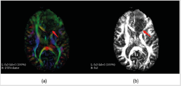
Figure 1: The tumor (red arrow) in DTI
a) And FA
b) Slices.
Segmentation of Fibers and Tumor
Tractography seeding module was employed to visualize the fibers in the slices based on fractional anisotropy (FA) images, the parameters were detailed in (Figure 2).
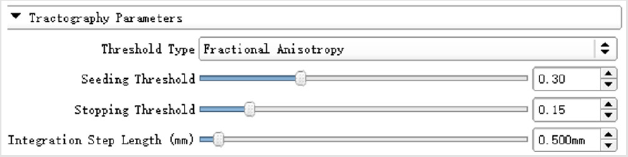
Figure 2: The parameters of tractography used in the visualization.
Dafeng Ji: birth in 1980, PhD, majority is the application of virtual reality in medicine.
Fibers Segmentation in Transverse Section: The first step is to depict the range in transverse section, an “O” shaped region was selected as peritumoral area to display the fibers, (Figure 3) shows the process and results of this step.
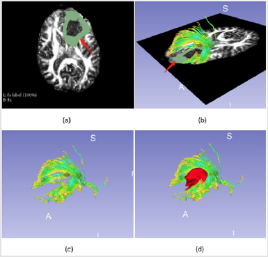
Figure 3: Fibers tractography based on manual label around tumor,
a) is the manual segment around tumor (red arrow),
b) shows the fibers visualization based on the segment (red arrow),
c) shows the fibers only and
d) illustrates the relationship between fibers and tumor.
Fibers Segmentation in Sagittal Section: Considering the direction of the fibers, the peritumoral region should include those in left-right direction which could be displayed in sagittal section, (Figure 4) shows the labeling process on sagittal section.
Fibers Identification
The fibers could be identified according brain atlas under brain tissue visualized. Meanwhile, VTK (virtual tool kit) models of fibers were exported and re-imported into slicer to find the position of the fiber in FA images (Figure 5 demonstrates).
Discussion
Selecting of the Range for Peritumoral Fibers Displaying
The function areas and fibers around tumor is very important for operation plan, the function area could be identified with functional MRI (fMRI) and diffusion MRI (dMRI) [1], the range of seed and selected region could affect the results of displaying the fibers around the tomur [2]. The occupation of tumor consist of a center and edema part, the center always shows a low intensity in T1 series, while the edema part has a little higher intensity than those in the center. It is necessary to identify the range of white matter to display the fibers around tumor. 3D Slicer supports a lot of modules such as segment, diffusion, and dMRI for segment, reconstruction and even fibers displaying functions [3-5]. In this paper, Diffusion module was employed to display the fibers, the authors drew a range with 10 mm width around the tumor. From Figure 3-Figure 5, the fibers could be displayed clearly and the special relationship between tumor and fibers is very clear. On the other hand, considering the direction of fibers, the label should be set both in transverse section (up-down going fibers) and sagittal section (left-right going fibers) which were approached in (Figures 3 & 4).
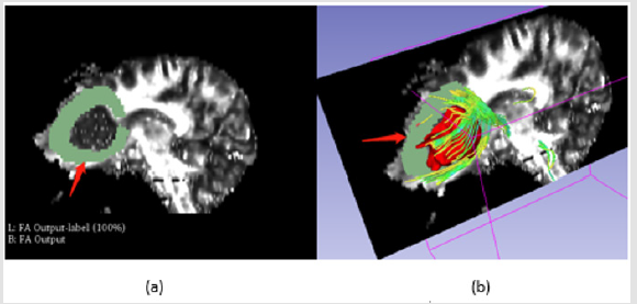
Figure 4: Fibers segmentation in sagittal section, a is manual label around the tumor as red arrow shows, b is the visualization of fibers.
Fibers Identification
Identifying the fibers is a key step to avoid dysfunction and improve the survival ratio after operation [6]. Brain atlas is always used to identify the fibers as Figure 5a-5c shows [7]. But it could only give a raw information about the fiber, as to identify the fiber in detail, the 2D projection of 3D model was approached in this paper. Fibers had been saved as vtk models and reimported into slicer, then, the fibers were displayed in Figure 5d-5g. 3D slicer 4.8.1 supports a key role in tumor and fibers visualization and identification. The diffusion module is very useful for displaying the fibers diffuse tensor imaging (DTI) via fiducial and label in tractography seeding tool kit.
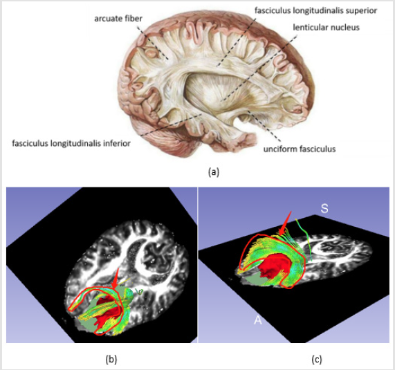
Figure 5a: Fibers identification,
a) is the white matter of brain (download from website),
b) is the fibers in corpus callosum which was disrupted by the tumor, and
c) is the arcuate fibers between superior frontal gyrus and inferior frontal gyrus,
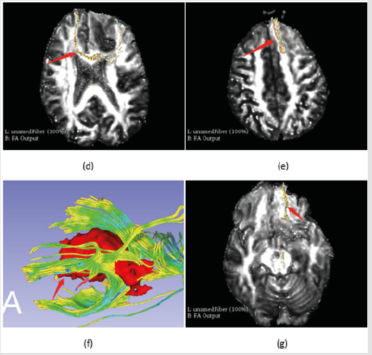
Figure 5b: Fibers identification,
d) and
e) are the VTK models which were displayed in transverse section respectively.
f) and
g) are the lower part fibers of corpus callosum from bottom aspect of the tumor.
Conclusion
Ranges labeled on transverse and sagittal sections could be used to visualize the fibers around tumor, vtk models of fibers could be used to identify the fibers.
Acknowledgement
This work is supported by 3D Slicer (www.slicer.org).
References
- E Bullmore (2012) The future of functional MRI in clinical medicine. NeuroImage 62(2): 1267-1271.
- A Radmanesh, AA Zamani, S Whalen, Tie Y, Suarez RO, et al. (2015) Comparison of seeding methods for visualization of the corticospinal tracts using single tensor tractography. Clin Neurosurg 129: 44-49.
- A Fedorov, R Beichel, J Kalpathy Cramer, Finet J, Fillion Robin JC, et al. (2012) 3D Slicer as an image computing platform for the quantitative imaging network. Magn Reason Imaging 30(9): 1323-1341.
- IF Talos, LO Donnell, CF Westin, Simon K Warfield, William Wells III, et al. (2003) Diffusion tensor and functional MRI fusion with anatomical MRI for image-guided neurosurgery. International Conference on Medical Image Computing and Computer-Assisted Intervention pp. 407-415.
- I Qguz, M Farzinfar, J Matsui, Budin F, Liu Z, et al. (2014) Dtiprep: quality control of diffusion-weighted images. Front Neuroinform 8: 4.
- JR Petrlla, LM Shah, KM Harris, Friedman AH, George TM, et al. (2006) Preoperative functional MR imaging localization of language and motor areas: effect on therapeutic decision making in patients with potentially resectable brain tumors. Radiology 240(3): 793-802.
- LJO Donnell, Y Suter, L Rigolo, P Kahali, Fan Zhang, et al. (2017) Automated white matter fiber tract identification in patients with brain tumors. NeuroImage Clinical 13: 138-153.
